

 Michael’s Corner #1
January 2003
Introducing Mr.Beall
By way of introduction, my name is Michael Beall and several years ago I contacted David Watson to thank him for recommending my book "AutoCAD R14 for Beginners" to the AutoCAD users at University of Greenwich. Since that time we have stayed in touch and just recently David invited me to contribute to his CAD Tutor website. "Michael's Corner" will be my monthly contribution to the AutoCAD-literate with the intent of making you "quicker, better, smarter, faster" or simply more informed.
If you would like to contact me directly, you can do that also.
Blessings to one and all,
Michael
Creating Custom Linetypes
Where's the Code?
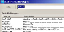 AutoCAD stores the code of all of the default linetypes in the file acad.lin. When you click on the linetype Continuous while in the Layer Properties dialog, the Select Linetype dialog opens. If you need a linetype that's not already in the drawing, you click on the Load button and the Load or Reload Linetypes dialog shows you all of the available linetypes which are contained in the acad.lin file. The trick is getting your own in there.
Tutorial for Making Your Own
Rule No. 1 with AutoCAD, of course, is to use what's available as a building block to make your own. In this exercise you create a custom linetype for Cold Water --CW--CW--CW--.
- Open the acad.lin file in Notepad. Notice there are two lines of code for each linetype. The first line begins with an asterisk followed by the name of the linetype (with no spaces in the name) and what amounts to the description of the linetype. The second line is the linetype's coded definition and begins with the letter 'A'. There are no options here. I'm sure, once upon a time, Autodesk was going to, but not now.
*HOT_WATER_SUPPLY,Hot water supply ---- HW ---- HW ---- HW ----
A,.5,-.2,["HW",STANDARD,S=.1,R=0.0,X=-0.1,Y=-.05],-.2
- Highlight the two lines of code for the Hot Water linetype and Copy/Paste it to the bottom of the acad.lin file.
- Edit the first line and change it to read as a Cold Water linetype description. This amounts to changing Hot to Cold in two locations, and changing the HW to CW.
- Edit the definition code. Since our new Cold Water linetype is virtually identical to the Hot Water, the edits in the second line are relatively easy, (change the HW to CW).
What follows is a review of the coded information for this new Cold Water custom linetype:
Second line must start with A.
Any positive number is 'pen down' and is the length of the line segment drawn between each CW occurrence. Any negative number is a 'pen up'. This specifies the length of the gap before the center point of the text.
[Bracketed information (with commas separating each item):
"CW" The text inserted in the line. You need to have it in quotes.
STANDARD The text style to be used for the inserted text. Please note that the style requested must exist in the drawing or the linetype cannot be displayed as defined.
S=.1 Text size if the text has not been preset in the requested text style. If the text style specifies a height for the text, the S value is the factor applied to that height.
 R=0.0 How the text is to be treated within the line. The R defines the Relative rotation of the text within the line. If you use A=, you specify the Absolute angle of the text, regardless of the angle of the line drawn.
X= and Y= This specifies the position of the insertion point of the text referenced from the midpoint of the text. You'll need to finesse this setting.
…End of bracketed items]
-.2 Another pen up to leave a gap after the center point of the text.
Making it Work
Save the acad.lin file, then launch AutoCAD. Create a layer for the Cold Water line, then click on the default linetype of Continuous to open the Select Linetype dialog. Click load and navigate down to your (alphabetized) Cold Water linetype, then select and assign it to the layer. Now when you draw on that layer, your CW linetype will appear!
Text Tips
This tutorial ran with the default 'Start from Scratch' launch of AutoCAD. If you work on larger drawings (AEC), consider the following settings:
Pen down 96 or greater (8')
Pen up (gap) 18 or greater
S (text size) 12 or greater
X -12
Y -6
If you make changes within the acad.lin file while a drawing is open, you can use the Ltype command (LT) to open the Linetype Manager dialog, then reload your custom linetype. Once the linetype has been redefined in the drawing, Regen and you will see the updated version. Per the above figure, the linetype follows Plines around so consider A=0 for the rotation.
Power Tool
Black and White and Back
In the Layer Properties dialog box starting in A2000i, the Save state and Restore state enable you to 'hold onto' the current condition or status of the drawing's layers.
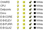
After setting the layer properties (Color, linetype, etc.) and their condition (On, Frozen, Locked, etc.), click Save state and name the layer state.
If you've made changes and you want to return to the named state's condition, use Restore state.
A common application is to save the original layer state when you get a drawing from an outside source. Another application may be to create a black and white condition before saving to a Word document.
The Odd Spot
Move + Copy Control
 You may not have encountered this yet, but if you simply select objects in a drawing, then left-click (pick) on them and drag them, you accomplish a move on those objects; no grips, no command, just click and run. If, however, you hold down Ctrl first, then pick and drag, you may see <Cycle on> staring at you on the Command line. This has to do with the 'object selection cycling' feature that has been around since R14 which involves holding down the Ctrl key when cycling through objects under a pickbox in an edit command. The odd thing is, the cycle feature appears with no command active. The solution is to simply initiate the activity as if you were moving the object(s), then hold down the Ctrl key as you are heading across the drawing.You will know it is in Copy mode if you see a little + sign beside your pointer as you are heading to the other location.
The Basics
Raster Images 101
Just what IS a 'raster image'? A raster image is essentially a collection of dots. Similar to a FAX, a raster image is nothing more than a highly sophisticated electronic collection of b/w or color pixels (picture elements) that make an image. Once upon a time there was VHS and Beta, and VHS came out the clear winner of the video format, at least in the USA. Contrary to that example, raster image file types abound. AutoCAD 2002 supports 14 different raster image formats that can be inserted into a drawing.
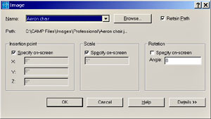 Although there is no 'winner' with respect to which format has a bigger share of the market, certain applications support their favorites based upon their requirements. When saving an image from a website, most images are either .jpg (a highly compressed image format), or .gif (a format that has been around since dirt). What can I do with them? If you have a digital picture of the product or the job site, go to the Layout, then choose Insert > Raster Image to open the Select Image File dialog. Navigate and select your image to open the Image dialog. Insertion point and Scale should be checked so you can place and size the image and the default rotation left at 0 (your call). Click OK and pick a point on the drawing, then move your cursor to size the image and pick a second point. You can use the grips on the corners to size it, too!
Donate to CADTutor
If you found this article useful, you might like to consider making a donation. All content on this site is provided free of charge and we hope to keep it that way. However, running a site like CADTutor does cost money and you can help to improve the service and to guarantee its future by donating a small amount. We guess that you probably wouldn't miss $5.00 but it would make all the difference to us.
Note from Michael: I want to thank all of my customers for continuing to retain my training services (some for over three decades!) and let you know your donations do not go to me personally, but to the ongoing maintenance of the CADTutor ship as a whole and to support the yeoman efforts of my friend and CADTutor captain, David Watson, to whom I am grateful for this monthly opportunity to share a few AutoCAD insights.
Share this page:


The Basics
- Dual Dimensions in a Dim…
- UCSICON Options
- "Best of" Basics: Irreg…
- Tool Palette Basics
- Original Dimension Value
- Possible Solutions to th…
- Avoid Using 'Standard' i…
- Shorten the Plot Scales…
- Update the Source File B…
- User Increment Angles fo…
- Drawing Information
- 'Sign Language'
- Rotate with the Copy Opt…
- Use the INSERT Osnap on…
- To or From the Current L…


