

 Michael’s Corner #92
August 2010
Random Features of Productivity
Now that The AutoCAD Workbench has been published and I'm back out on the road training pretty extensively, I went back through all the little sticky notes I have squirreled away and figured I better start getting them into print. The new hatch features in AutoCAD 2011 are very cool, so I wanted to review a couple of those, and then one of the AutoCAD powerheads at Lawrence Berkeley Labs came to me with a quandry that I think we were able to fix with the old ‘Cookie Cutter Trim’ feature.
Now that I got it all put together, here's what's in store for August 2010:
…Setting a new Origin and Rotating the hatch in AutoCAD 2011
…‘Cookie Cutter Trim’ is still around in the EXTRIM command
…Insights to the Navigation Cube, SNAPANG, & the A2010 Status bar
…Measuring an Area with the Measuregeom command
And if you have yet to do so, you can order The AutoCAD Workbench from my website using PayPal or download the order form.
Hope your summer is going well. Last week I was in Florida and this week I'm in Alaska; corner-to-corner. I have a lot of webinars in August, so I'm looking forward to just sticking around the house for a few weeks.
If you would like to contact me directly, you can do that also.
Blessings to one and all,
Michael
A2011 Hatch Tricks: Set a New Origin & Spin it
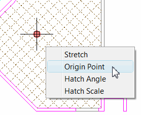 AutoCAD 2011's revamped Hatch routine has a couple really productive features that are driven from the hatch origin. When you hover on the round grip of the A2011 hatch, you get a shortcut menu. The options for Origin Point and Hatch Angle are each very intuitive and get the job done much more quickly than in previous versions.
The following exercise uses (my favorite), db_samp.dwg, located in the ..\Sample\Database Connectivity folder of A2010 and A2011, or the ..\Sample folder of every other version that has a pulse.
How to Set a New Hatch Origin
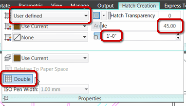
Create a layer for the hatch, then launch the Hatch command and configure the parameters as shown in this figure.
Note: For a review of the A2011 hatch command, take a look at Michael's Corner from April 2010. You will also find an extensive review of the AutoCAD 2011 Hatch command beginning on page 39 of The AutoCAD Workbench.
After configuring the hatch, click in the space where you want to add the hatch, then press [Enter] to complete the command.
To reposition the hatch by specifying a different origin point, click on the hatch to display the round grip in the geometric center.
Hover in the grip (don't click, just stay on it), and you see the shortcut menu shown in the opening figure, above.
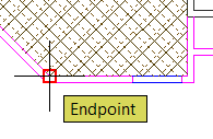 Click Origin Point, then use an object snap - Endpoint in this example - and specify the point you want to use as the new hatch origin. How easy is that!?
To modify the angle of the hatch, there are actually two methods. One approach would be to adjust the Angle from the context tab when you have clicked on the hatch. The other way would be to use the Hatch Angle option of the shortcut menu… both of which are equally entertaining.
How to Rotate the Hatch: Two Methods
 Click on the hatch to display the Hatch Editor context tab.
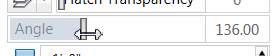
On the Properties panel, use the Angle slider to dynamically ‘rotate’ the hatch around the origin point.
To rotate the hatch with the shortcut menu, hover in the dot grip, the click Hatch Angle.
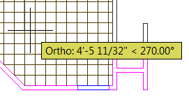 If Ortho is off, you can free-wheel the hatch around the origin. Turn on Ortho (when you're done playing with it), then click to complete the command.
Power Tool
The Old ‘Cookie Cutter Trim’ Still Around in EXTRIM
Lawrence Berkeley Labs have hundreds of drawings, most of which have multiple layout tabs. My friend there was looking for a way to document these plans and the general idea was to just ‘grab’ specific areas, then use the Wblock command to create a drawing of just that area. [See Michael's Corner, June 2006, or p. 79 in The AutoCAD Workbench for more on Wblock.]
You will need to open a drawing and then consider using SaveAs as you experiment with this command.
Note: This routine cannot trim blocks or Xrefs, so you will need to first Bind or Explode the geometry to be trimmed.
How to Use EXTRIM to Trim Objects on the Outside
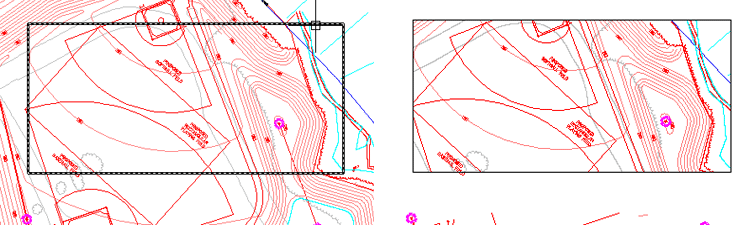
Create a Rectangle or a Circle around the area of the drawing you want to essentially isolate or ‘grab’.
Enter EXTRIM, and you will see the following prompt:
Pick a POLYLINE, LINE, CIRCLE, ARC, ELLIPSE, IMAGE or TEXT for cutting edge...

After you select the object to be the cutting edge, you see the following:
Specify the side to trim on:
Click on the inside or outside of the object being used as the cutting edge and AutoCAD trims the intersecting objects.
 In the opening figures of this article, you will see the result if you trim the objects on the outside of the rectangle. The third figure displays the result if you specify the inside of the rectangle as the side to trim on.
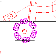
In this detail figure, you will see that the block was not trimmed.
The Odd Spot
Navvcube, Snapang, & A2010 Status
 The "Notes to Self" I have been keeping over the last few months are getting heavy on the Odd Spot list, so this month I decided to pile on.
NAVVCUBE Setting
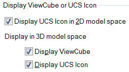 In AutoCAD 2010, the View Cube settings in the Options dialog box indicated that the View Cube was exclusively used in 3D Model space, as shown in the figure on the left from the A2010 3D Modeling tab of Options.
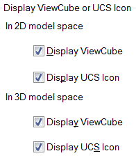 In AutoCAD 2011, however, by default, the View Cube is On in 2D Model space each time you launch AutoCAD or open a new drawing… unless you change the settings on the 3D Modeling tab of Options, shown here on the right.
Note: The variable NAVVCUBE also governs the display of the View Cube, but curiously, only if the box is checked under In 2D Model space for Display ViewCube. Not sure why the variable doesn't toggle the check box; that's the odd bit about this.
SNAPANG Setting
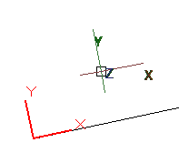 As many of you know, you can use UCS
![]() Object option to re-orient the User Coordinate System such that the X-axis is aligned with the selected object. This is shown in the figure on the right. [See Michael's Corner, August 2004, or the UCS coverage beginning on p. 21 in The AutoCAD Workbench.]
Object option to re-orient the User Coordinate System such that the X-axis is aligned with the selected object. This is shown in the figure on the right. [See Michael's Corner, August 2004, or the UCS coverage beginning on p. 21 in The AutoCAD Workbench.]
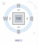
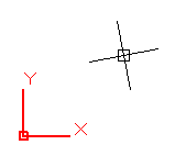 It is possible, however, to have ‘skewed’ crosshairs even if the current setting for the UCS is
 <World> (indicated by a box on the XY UCS icon), as shown here on the left.
The culprit: SNAPANG. To straighten the orientation of the crosshairs so they are parallel to the UCS, set the SNAPANG variable to 0. Curiously, this variable is not in Options and can only be modified from the Command line.
Status Bar Checklist in AutoCAD 2010 Only
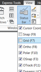 For a brief moment in AutoCAD's recent history - specifically AutoCAD 2010 - you could toggle on and off items on the Status bar from a list of check boxes! On the View tab
![]() Windows pane there is actually a Status Bar tool which drops down a check box list.
Windows pane there is actually a Status Bar tool which drops down a check box list.
I thought that was fabulous, because the only other way to toggle off unwanted Status bar features was to right-click on the status bar and toggle them off one at a time from the shortcut menu.
But, alas, that feature is not in A2011. Not really worthy of a Wish List for future releases, but something that I thought was kind of cool.
The Basics
The Area Option for Measuregeom
 Last month we looked at the "Multiple Points" option for the Distance feature of the Measuregeom command. This month we look at the "Area" option.
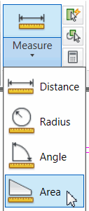
The Utilities panel of the Home tab displays the Measure drop-down list. From that list, we will be using the "Area" option.
How to Find the Area of a Space
Zoom up to an area you would like to calculate, then click the Measure drop-down list, then click Area.
-
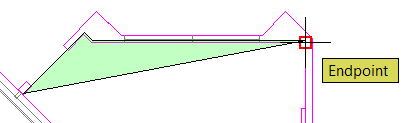
Turn on the Endpoint snap, then click around the inside corners of the room. You will see an expanding green shape displayed as you click around the room.
-
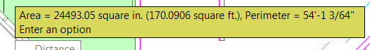
When you've gone all the way around, right-click and you will see the area information in a mustard colored window. Hit ESC to end the command and you will then see the calculation in the Text Window (or on the Command line if you scroll it up).
Note: After completing the Area command, hit F2 to open the Text Window. Highlight the desired calculations, then right-click and select Copy. Close the Text Window (F2), then use Paste [Home tab![]() Clipboard panel] and paste the contents into your drawing. Edit the Mtext as desired.
Clipboard panel] and paste the contents into your drawing. Edit the Mtext as desired.
Left Field
Boeing Plant 2 - A Fun Fact for the Farewell:
I just spent some time in Seattle with my customers at BINW and saw in the local paper that Boeing's Plant 2 is facing demolition. This was the monstrous space (large enough to hold 8 football fields) in which the B-17 bombers - the Flying Fortress - were built for WWII. Closed for over 40 years now, here's the historical note I found fascinating:
"Although the plant's greatest achievements lie in the aircraft it produced, most notably the nearly 7,000 B-17 Flying Fortress bombers built here, a favorite story about the facility involves what was on its roof: a fake neighborhood. Houses, streets and plants were assembled like stage props out of plywood, clapboard, chicken wire and burlap, covering the plant's roof during World War II. If any Japanese bombers made it this far east, the hope was that their pilots would mistake this for a quiet residential neighborhood." (Originally published July 25, 2010 at 8:47 PM, The Seattle Times)
Donate to CADTutor
If you found this article useful, you might like to consider making a donation. All content on this site is provided free of charge and we hope to keep it that way. However, running a site like CADTutor does cost money and you can help to improve the service and to guarantee its future by donating a small amount. We guess that you probably wouldn't miss $5.00 but it would make all the difference to us.
Note from Michael: I want to thank all of my customers for continuing to retain my training services (some for over three decades!) and let you know your donations do not go to me personally, but to the ongoing maintenance of the CADTutor ship as a whole and to support the yeoman efforts of my friend and CADTutor captain, David Watson, to whom I am grateful for this monthly opportunity to share a few AutoCAD insights.
Share this page:


The Basics
- Dual Dimensions in a Dim…
- UCSICON Options
- "Best of" Basics: Irreg…
- Tool Palette Basics
- Original Dimension Value
- Possible Solutions to th…
- Avoid Using 'Standard' i…
- Shorten the Plot Scales…
- Update the Source File B…
- User Increment Angles fo…
- Drawing Information
- 'Sign Language'
- Rotate with the Copy Opt…
- Use the INSERT Osnap on…
- To or From the Current L…


