

 Michael’s Corner #64
April 2008
Customizing and Discovering
As you know, I'm passionate about palettes (professionally speaking), so I have finally gotten around to covering how to add another block as a visibility parameter on a dynamic block (which imminently ends up on a tool palette). I'm also keeping the ball rolling with yet another custom button on the tool palette; this one you can call "Wall Maker" or "Duct Worker" or whatever suits your particular application.
The discoveries I wanted to pass along are those related to layer filters and PDF files. I read an article in an eNewsletter that I subscribe to through Cadalyst which spoke about the Filters command that can be used to keep or delete layer filters you may encounter in a drawing you receive. Then one of my students was asking about bringing a PDF into AutoCAD, and when you think about it, it's nothing more than inserting it as an OLE object. Both of those I thought were pretty slick and I hope you agree.
I hope these insights bump your productivity a bit today so you can have a few more minutes with your family or favorite activity.
If you would like to contact me directly, you can do that also.
Blessings to one and all,
Michael
Adding Another Block as a Visibility Parameter
The easiest dynamic block feature - for me - is the Visibility Parameter. The result is essentially several blocks within one block. All that's required is to make more than one block, place them on top of each other, then make a list and connect the right block to the right name. OK, that's the Reader's Digest version, but it really is that simple (see Michael's Corner, July 2006).
The question comes when you need to pile on and add another block to the currently defined dynamic block. The following presumes you have a dynamic block with multiple visibility parameters and have made another block to add to it. In the exercise, I add a Quad receptacle to an existing dynamic block.
Instructions to Include Another Block as a Visibility Parameter
- After creating another block you want to add to the dynamic block, double-click the dynamic block to open the Edit Block Definition dialog box, then click OK to go into the Block Editor environment.
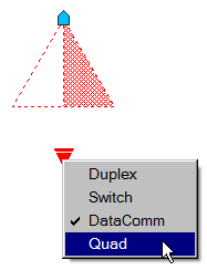
- Set the appropriate layer (the layer on which you want to insert the block), then launch the Insert command and insert the new block you want to include. In this exercise, I insert the new block I created named "Quad". Be sure to insert the block at the same insertion point as the other blocks.
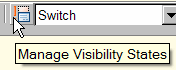 To add a new visibility state (for the new block), click Manage Visibility States, then click New and add the name you want to use for the new block, then click OK. (It doesn't have to be the name of the block itself, but it's more intuitive if you do.)
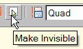 When you opened the Block Editor in Step 1, one of the blocks is visible, of course. Now that you have inserted the new one, you probably see two. To isolate the new block from the one that was already there, click Make Invisible, then click the block that had been there (to make it invisible), leaving the new block associated with its visibility state in the drop-down list.
Note: It would be a good idea to cycle through the other visibility states, just to make sure their states are properly configured. Use Make Invisible as necessary.
- Click Close Block Editor and save the changes. Click your dynamic block, then click the visibility parameter icon to see the list… including the new block!
Note: For a review of how to add an Alignment Parameter, see the Power Tool, November 2005.
Power Tool
Custom Button #6: Double-Line [Dline]
This month we'll put the Dline routine on a button with a pre-assigned Width for creating a wall, justification (Dragline option) and Layer. For more on this wonderful little tool, take a look at August 2003 (where you can also download Dline.lsp) and the Odd Spot in September 2005.
Instructions to Add Properties to a Button for Creating a Dline
- Open the Tool Palette window, then you will need a blank button to work with (see Odd Spot, April 2007).
- Right-click on the blank button, then click Properties to open the Tool Properties dialog box.
- Edit the Command String to read as shown below. In the example, I have the width set to 6″ as a sample wall width, but you can put whatever value you want in there as shown in my example below for ductwork.
^C^CDLINE;W;6;D;R
Text Character Reference
| ; | Presses Enter; it's easier to discern a semi-colon than a space when pressing Enter in a macro. |
| W | The Width option of the command. |
| D | The Dragline option which enables you to specify the Justification of the wall. |
| R | Right justified based upon the direction of "travel" as you're picking each point of the Dline. |
- Under the General section, change the Layer property to the desired layer, then set the Color and Linetype properties to ByLayer. While you're in the Tool Properties dialog box, you may want to change the Name of the button and perhaps add an image.
Tip: Using Dline for Mechanical Ductwork…
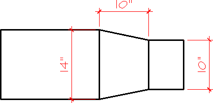
When creating ductwork using Dline, I would set the Dragline to Center, but remember that you can change the width of the double-line while the command is still active. This is great if you want to transition, say, from a 14″ duct to a 10″ duct. The result, however, is a notch rather than the proper look of a transition or reducer section of ductwork, as shown in the first illustration, below.
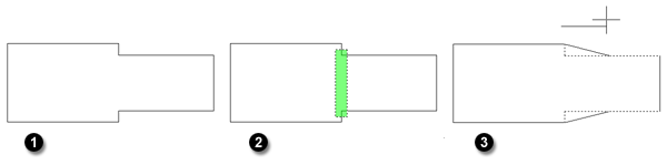
To resolve this - and to create the proper length for the transition - after completing the Dline command, use the Stretch command to stretch the transition "notch" to the appropriate length. (See May 2006, Basics for coverage on using Stretch.) After stretching the transition, use the Line command to add the lines between sections as shown in the dimensioned illustration. [My thanks to Tim at KLM Mechanical for his industry expertise, www.klm-mechanical.com.]
The Odd Spot
FILTERS and LAYEREVAL
Although many of the AutoCAD tips and insights in my articles come from things I think of while presenting my training courses across the country, I also subscribe to Cadalyst Magazine's Tips & Tools Weekly.
In one of those weekly eNewsletters several months ago, Faith Merriman (Mullins & Sherman Architects, Sanford, NC) sent in a tip that I really have to pass along to you all. In the product formerly-known-as Architectural Desktop, there was a buried command that also goes back to at least AutoCAD 2006.
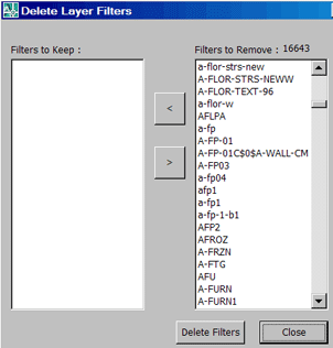
The FILTERS (plural) command opens a dialog box that enables you to Keep or Remove all those snarky layer filters you may encounter when receiving a drawing from another vertical market version.
Got Unreconciled Layers?
As for that Unreconciled Layers notice you may have encountered, AutoCAD's Help database has the following review of the LAYEREVAL variable. For a broader review of related Unreconciled Layer topics including Concept and Procedure, go into Help and Search on this variable.
LAYEREVAL: Controls when the Unreconciled New Layer filter list in the Layer Properties Manager is evaluated for new layers. The setting is stored in an integer using one of the following values:
0 - Off
1 - Detects when new Xref layers have been added in the drawing
2 - Detects when new layers have been added in the drawing and Xrefs
The Basics
OLE a PDF
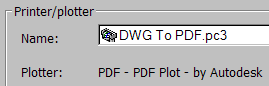
AutoCAD 2008 first introduced a PDF driver developed by Autodesk by which you can print a PDF from within AutoCAD, but I'm beginning to get questions on how to bring a PDF into an AutoCAD drawing.
How about we insert it as an OLE object, shall we?
Instructions to Insert a PDF as an OLE Object
- Click Insert
 OLE Object to open the Insert Object dialog box.
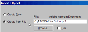
 - Click the Create From File radio button, then click Browse and navigate to the desired PDF file, then click OK.
- Specify the insertion point for the OLE image. To size the image, click on it and use the grips.
Left Field
Banana Strings - I'm not sure where my son said he heard this, but if you peel a banana from the bottom up, those stringy parts peel off with the peel itself. Thanks, Bear! You Rock!
Donate to CADTutor
If you found this article useful, you might like to consider making a donation. All content on this site is provided free of charge and we hope to keep it that way. However, running a site like CADTutor does cost money and you can help to improve the service and to guarantee its future by donating a small amount. We guess that you probably wouldn't miss $5.00 but it would make all the difference to us.
Note from Michael: I want to thank all of my customers for continuing to retain my training services (some for over three decades!) and let you know your donations do not go to me personally, but to the ongoing maintenance of the CADTutor ship as a whole and to support the yeoman efforts of my friend and CADTutor captain, David Watson, to whom I am grateful for this monthly opportunity to share a few AutoCAD insights.
Share this page:


The Basics
- Dual Dimensions in a Dim…
- UCSICON Options
- "Best of" Basics: Irreg…
- Tool Palette Basics
- Original Dimension Value
- Possible Solutions to th…
- Avoid Using 'Standard' i…
- Shorten the Plot Scales…
- Update the Source File B…
- User Increment Angles fo…
- Drawing Information
- 'Sign Language'
- Rotate with the Copy Opt…
- Use the INSERT Osnap on…
- To or From the Current L…


