

 Michael’s Corner #84
December 2009
…and December Makes Seven
By the time this is posted, Autodesk University 2009 will be in the books and several thousand users of Autodesk products will be on sensory overload, myself included. Over the next few months I'll be sure to pass along some of the "Best Bets" that I came away with from the sessions I attended. I am also considering including occasional coverage on Revit since so many of my customers have encountered firms providing and requesting Revit-generated drawings.
As is often the case, my topics this month lean heavily upon the requests, comments, and encounters of those customers, and this month they include:
…Adding a drop-down list of 3D commands to the Quick Access Toolbar
…Creating a customized hatch pattern with the Express Tools command, ‘Superhatch’
…An important follow-up to the September coverage of DIMASSOC
…The wisdom of using the Rectangle command rather than Pline to create& the lowly rectangle
And so this December completes the 7th year of Michael's Corner. Hopefully, I can have a book in your hands - either an eBook or printed media - before summertime that contains the last seven years of tips and insights, updated to AutoCAD 2010. That's my goal this year, so stay tuned.
Blessings to one and all for a very Merry Christmas and a joyful and exciting New Year!
If you would like to contact me directly, you can do that also.
Blessings to one and all,
Michael
Adding a 3D Modeling Dropdown to the Quick Access Toolbar [A2010]
 There are two primary Ribbon-based Workspaces in A2010 - 2D Drafting and Annotation and 3D Modeling. So how about we take an item from the 3D Modeling workspace and add it to our Quick Access Toolbar!?
Instructions to Add and Edit a Quick Access Toolbar Dimension List
Click Workspace Switching (on the right-hand side of the Status bar), then click 3D Modeling to change the Ribbon content to that particular collection of tabs.
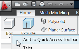
 On the Home tab, the first panel is Modeling. Right-click on Box, then click Add to Quick Access Toolbar.
To modify that list of modeling commands, enter CUI to open the Customize User Interface.
Expand each of the Quick Access Toolbar nodes, then expand the Solid Primitives Drop-down node to see the list of the modeling commands.
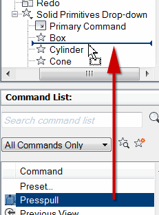 To add another 3D command to the list - for example, Presspull - in the Command List, drag up the Presspull command and release it in the list of Modeling commands.
Click OK to apply the changes and close the CUI.
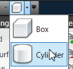
Now in the Quick Access Toolbar, click the Modeling Drop-down to see the addition of the Presspull command! It will still be there when you go back to the 2D Drafting and Annotation workspace, too.
Note: Hopefully, this has sparked some interest for some of you regarding building a drop-down menu for the Quick Access Toolbar that contains your favorite commands!
Power Tool
SUPERHATCH [Express Tools]
 It is not easy to create your own custom hatch, so when the SUPERHATCH feature came out years ago - I think it originally showed up in the Bonus Tools - I was quite pleased. The big plus is that you can "hatch" an area with something as simple as a block. Here's how…
Instructions to Create and Add a Custom Hatch with SUPERHATCH
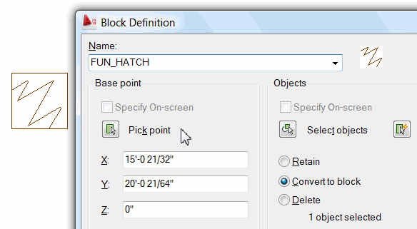
On the desired layer, create a 12″ x 12″ rectangle (if you are not familiar with the Rectangle command, see this month's Basics).
Within the square, use the Polyline command and create any shape you want.
-
Use the Block command and select the Polyline only when you "Select Object", and specify the lower left corner of the rectangle as the Pick Point.
Now create any closed shape. This will be the area within which you will be adding the hatch, (so it should be significantly larger than your 12 x 12 block).
 From the Express Tools menu/tab, click Draw
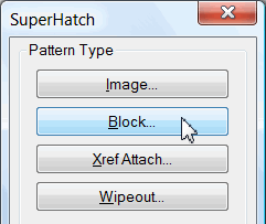
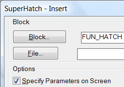
 Super Hatch to open the Superhatch dialog box, then click the Block button.
With Specify Parameters on Screen checked, click OK.
Just to get familiar with the process, pick a point in the lower left corner of your closed shape, then press [Enter] for the default values of the X and Y Scale factor <1> and the Rotation <0>.
Press [Enter] for <Yes> when prompted "Is the placement of this BLOCK acceptable". You will then see the following prompt:
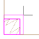
Select a window around the block to define column and row tile distances.
Current rectangle modes: Width=0'-0 1/4"
Specify block [Extents] First corner <magenta rectang>:If you press [Enter], the end result of the Superhatch process will array the block corner to corner, per the illustration below left.
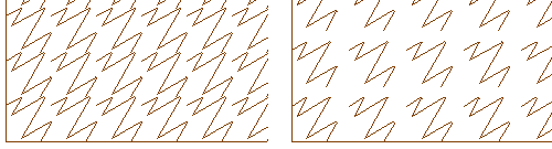
To provide a gap between the placement of each of your hatch blocks (as shown in the illustration above right), pick two points - beginning with the lower left corner of the magenta rectangle - making a rectangle a bit larger than the default, as shown here.
 After picking the second corner, press [Enter] and you will see the following prompt:
Specify an option [Advanced options] <Internal point>:
Pick a point within the closed shape you created in step 4, then press [Enter] to complete the command.
It may take you a few tries to get the hatch exactly the way you want it, but I think you will really enjoy the results.
The Odd Spot
DIMASSOC Follow-up: DIMDISASSOCIATE (seriously)
In the Odd Spot from Michael's Corner, September 2009, I presented the variable DIMASSOC and gave a practical application of where that may be used. So far, so good.
 Then, when I was training Bialek Environments in Rockville, MD, one of the designers asked me how to disable the ‘follow’ feature incurred when you have Dimassoc set to <2>. Good question… and I had no answer and told her I would have the answer in an upcoming article…
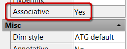
Curiously, you can't change the Associative condition of the selected dimension in the Properties dialog box (notice in this illustration that the Associative feature is not ‘live’).
Answer: DIMDISASSOCIATE, then select the offending dimension.
The Basics
The Lowly Rectangle
Using the Rectangle command is a much more effective method of creating rectangles than using Polyline, so let's look at the two approaches to creating that rectangle. In each of the following procedures, you will create a rectangle that is 12′ x 4′ (…about the size of your Thanksgiving table if all the leaves are in).
Instructions to Create a Rectangle - Old School
Launch the Rectangle command (Ribbon: Home tab, Draw panel), then specify the first corner.
At the prompt to "Specify other corner point…", type @12′,4′ then press [Enter]. The command is now complete and you have a rectangle.
Note: Whenever AutoCAD is ‘asking’ for the placement of the next point - such as the placement of the second corner of the rectangle - you can enter the location of that next point in the format of @X,Y. Think of the @ sign as going from where you're ‘at’, then enter how far over in X (the horizontal direction) and Y (the vertical direction).
A negative values for X will go to the left, a negative value for Y will go down. In step 2, above, if you entered @4′,12′, your rectangle would be vertically oriented; try it.
Instructions to Create a Rectangle - "Dimensions" Option
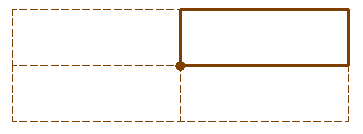
Launch the Rectangle command, then specify the first corner (the location of the dot in the illustration).
At the prompt to "Specify other corner point…", enter D for the Dimensions option. (When using the Dimensions option, you need not specify a positive or negative direction, simply the physical dimensions of the rectangle.)
When prompted to "Specify length for rectangles…", enter 12′.
When using the Dimensions option, the first prompt is always for the Length and the value entered will be for the dimension of the rectangle horizontally (in the X axis).
When prompted to "Specify width for rectangles…", enter 4′.
When using the Dimensions option, the second prompt is always for the Width and the value entered will be for the dimension of the rectangle vertically (in the Y axis).
Now, since you did not need to numerically specify a direction for that rectangle, you have the opportunity to move your cursor into any one of the four quadrants adjacent to the first corner specified (the dashed rectangles in the illustration).
Position your cursor in the desired quadrant, then click to place the rectangle and complete the command!
Also, you will find additional coverage on graphically specifying points for the Rectangle command in Michael's Corner, September 2005.
Left Field
The Wonder of the Stars: I love looking at the stars and my favorite is the Big Dipper. I thought it was really cool when I came across some constellation names in the Bible, "He is the Maker of the Bear and Orion, the Pleiades and the constellations of the south." [Job 9:9] But what I really found to be awesome… is that God has counted and named 'em all: "He counts the number of the stars; He calls them all by name." [Psalm 147:4] Merry Christmas to you and yours!
Donate to CADTutor
If you found this article useful, you might like to consider making a donation. All content on this site is provided free of charge and we hope to keep it that way. However, running a site like CADTutor does cost money and you can help to improve the service and to guarantee its future by donating a small amount. We guess that you probably wouldn't miss $5.00 but it would make all the difference to us.
Note from Michael: I want to thank all of my customers for continuing to retain my training services (some for over three decades!) and let you know your donations do not go to me personally, but to the ongoing maintenance of the CADTutor ship as a whole and to support the yeoman efforts of my friend and CADTutor captain, David Watson, to whom I am grateful for this monthly opportunity to share a few AutoCAD insights.
Share this page:


The Basics
- Dual Dimensions in a Dim…
- UCSICON Options
- "Best of" Basics: Irreg…
- Tool Palette Basics
- Original Dimension Value
- Possible Solutions to th…
- Avoid Using 'Standard' i…
- Shorten the Plot Scales…
- Update the Source File B…
- User Increment Angles fo…
- Drawing Information
- 'Sign Language'
- Rotate with the Copy Opt…
- Use the INSERT Osnap on…
- To or From the Current L…


