 Michael’s Corner #39
March 2006
More 3D Orbit, more programming… and an AutoCAD 2007 tidbit
Yep, there's a new kid on the block; AutoCAD 2007 was released to the world on March 1st. You will find all kinds of information at the mothership, www.autodesk.com, as well as the AUGI website, www.augi.com.
In the meantime, for those of us in the trenches, I wanted to elaborate upon my 3D Orbit article a bit by showing you a little-known procedure that enables you to generate interior elevations. AutoCAD 2007 is chock full of 3D related features … material libraries, sample libraries, light placement, etc. … so I hope this review will help you become a bit more 3D savvy. The A2007 tidbit I threw in was the fact that A2007 now has a DWG to PDF driver for plotting. But for those of us needing to send a drawing to folks without AutoCAD, I think the WMFOUT routine that has been around for many versions will be one you may want to consider.
This month I also follow-up my review of the ACAD.PGP file with how to capture your AutoCAD variables, then reinstate them if you have to re-install AutoCAD. The routine has been around for quite some time. Those of you jumping on the A2007 bandwagon will also find it useful to capture your variables once you load up A2007 and get it just the way you like it. And finally, something that came up in training just this week regarding palettes that I wanted to make sure everyone understood. Specifically, the importance of a unique source file for your palette blocks.
If you would like to contact me directly, you can do that also.
Blessings to one and all,
Michael
Elevations Using 3D Orbit
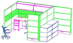 Last month I showed you a bit about the fundamentals of 3D Orbit. Let's go one more step and see how you can get an interior elevation of a 3D space. Since I work quite a bit with the contract furniture industry, I'm going to use an 8' x 8' workstation as an example.
If you would like me to send you the 3D drawing I am using in this exercise, email me and ask for the "3D Workstation".
Let's say you want to want to walk into the workstation and turn to your right such that you're looking from the left toward the right. Here's how to make it happen:
Instructions to Get an Interior Elevation with 3D Orbit
First… Open your 3D drawing and launch the 3D Orbit command.
Next… Right-click for the shortcut menu, then click . You're on the outside on the left, but at least you're looking the proper direction.
Then… Right-click for the shortcut menu and click to open the Adjust Clipping Planes dialog box. Your 3D drawing will appear in plan view with a horizontal line above and below the plan. The one below is the Front Clipping Plane; the one above is the Back Clipping Plane.
Now… Click the button for Front Clipping On/Off to turn on the clipping plane (the one at the bottom).
And… Put that funny looking cursor on the horizontal line of the Front Clipping Plane and drag it north … slowly. In the drawing you will see the 3D objects being clipped as you drag that line into the workstation.
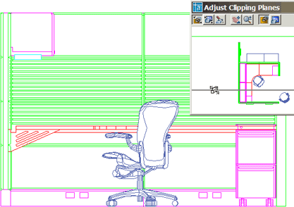
After you close the Adjust Clipping Planes window and Exit 3D Orbit, smart money says you will save the view by name. Take a look at the Basics section from June 2003 if you're unfamiliar with that procedure.
Is that fabulous or what!!
Power Tool
Retaining System Variables
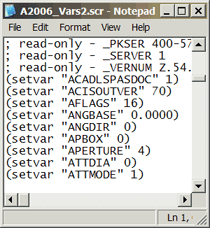
When (not if) AutoCAD needs to be re-installed, what do you do to hold onto your settings? Of course, you have your template (.DWT), and perhaps you have created a Profile (See October 2003). But what about all the system variables?
There's a routine called VARS2SCR that automatically gathers all your AutoCAD variables (Registry variables as well as Drawing-specific) and creates a .SCR file. Since the drawing-specific variable are also gathered at this time (such as FILLETRAD and TEXTSIZE), you will want to configure those first. For a list of most of the variables this routine captures, if you have AutoCAD 2004 thru A2007, go to
Instructions to Create and Use the VARS2SCR routine
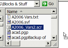
- At the command line, enter VARS2SCR.
- Navigate to the folder where you want to save this file and give it a name such as A2006_VARS-yourinitials. The figure shows a portion of the content of the SCR file.
- To test it, set the variable CURSORSIZE to something like 27.
- Open Windows Explorer and navigate to the folder containing the SCR file.
- Now drag the .SCR into the AutoCAD drawing window and you should see the cursor size change back to the size saved in the script file.
The Odd Spot
AutoCAD and the Windows Metafile format
 What do you do when you need to get a drawing to someone electronically who doesn't have AutoCAD? There are numerous solutions, including the creation of a DWF (Design Web Format) as well as the new AutoCAD 2007 DWG To PDF feature that lets you create a PDF from a DWG…
you heard it here first!
But I digress…
There's a routine called WMFOUT that creates a WMF file that is extremely clear and creates a very small file; much smaller than the other available raster image formats generated using JPGOUT, TIFOUT, and BMPOUT. The downside is that you need to select objects and that tosses out the ability to use it in a layout. Nonetheless, it's a great alternative when you want to simply capture objects in a drawing and paste them into Word.
Here's an example WMF for you to try: stair.wmf - right-click and select "Save Target As…" to download ("Save Link As…" if you're using Firefox).
Instructions to Create the WMF and Insert it into Word
- In Model Space, zoom up to the objects you want to select for the WMF.
- At the command line, enter WMFOUT, then select the objects and press [Enter].
- Navigate to the desired folder and name the file, then select the objects.
- Open Microsoft Word® and use to insert the WMF file.
- Open the Picture toolbar in Word and use the Crop and Text Wrapping tools as necessary.
The Basics
The Importance of the Palette Source File
Have you ever been working along and wrote down the steps to do something and thought, "Ooh, I have to make sure I pass that along"? I was training the wonderful design team from the Madison & Milwaukee offices of Interior Investments when I put something on the board that is a great tip when using the tool palette.
Scenario: Someone sends you a drawing and in that drawing you see a really cool block that you would like to add to you tool palette.

Problem: If you drag and drop that block directly onto your palette from the drawing (A2005 & A2006 only; A2004 users have to do it from DesignCenter), you have established that drawing as the "source drawing" for the block. If the drawing is renamed, archived, or deleted, the block on your palette is… "toast" (I put that in for my friend in Sao Paulo).
Suggestion: Don't drag anything onto your palette from a drawing that you can't keep track of. Put it in a drawing you have dedicated as a source drawing for all your blocks. Let's say you have one called Block_Source.dwg…
Instructions to Efficiently Add Blocks to a Palette
- Open the drawing with the cool block.
- Open your source file, Block_Source.dwg.
- Tile your drawings vertically using .
- Click on the cool block, then click and drag it into the source file.
- Save the source drawing.
- Drag cool block to the palette. Job done.
Left Field
Taxi! To become one of the nearly 24,000 taxi drivers in London, you need to master The Blue Book, the single manual for a course that takes between 2 and 4 years to complete. (You have a whole new appreciation for those mates now, don't you?)
Donate to CADTutor
If you found this article useful, you might like to consider making a donation. All content on this site is provided free of charge and we hope to keep it that way. However, running a site like CADTutor does cost money and you can help to improve the service and to guarantee its future by donating a small amount. We guess that you probably wouldn't miss $5.00 but it would make all the difference to us.
Note from Michael: I want to thank all of my customers for continuing to retain my training services (some for over three decades!) and let you know your donations do not go to me personally, but to the ongoing maintenance of the CADTutor ship as a whole and to support the yeoman efforts of my friend and CADTutor captain, David Watson, to whom I am grateful for this monthly opportunity to share a few AutoCAD insights.
The Basics
- Dual Dimensions in a Dim…
- UCSICON Options
- "Best of" Basics: Irreg…
- Tool Palette Basics
- Original Dimension Value
- Possible Solutions to th…
- Avoid Using 'Standard' i…
- Shorten the Plot Scales…
- Update the Source File B…
- User Increment Angles fo…
- Drawing Information
- 'Sign Language'
- Rotate with the Copy Opt…
- Use the INSERT Osnap on…
- To or From the Current L…


