

 Michael’s Corner #20
August 2004
UCS: It's Yours - Use It!
The User Coordinate System is overlooked frequently when, in fact, there's lots of power if you know where to look. This month we take a look at a few of the integral parts of this feature. Also this month I just wanted to mention that there's a whole array of "underground" features that can be found on just the Command line. If you have some favorite Command line only routines that you can't do without, pass 'em along.
If you would like to contact me directly, you can do that also.
Blessings to one and all,
Michael
UCS: Not Just for 3D Drawings
In an effort to dispel the overriding myth that the UCS deserves to be turned Off unless you're working in 3D, I'd like to show you a very simple yet powerful 2D application.
Life doesn't hand us perfectly orthogonal drawings all the time. For those unique situations – or not so unique situations in the mapping and civil engineering fields – the following procedure will enable you to bring a non-orthogonal line to be horizontal in the drawing window.
 |
 |
 |
Instructions for using the UCS to "rotate" the drawing view
- Turn on the UCS icon (View
 DisplayUCS IconOn), if it isn't already.
 - Set the UCS icon to the Origin using ViewDisplayUCS IconOrigin. This will enable you to understand what's happening a bit easier.
- To align the User Coordinate System with an existing line, use ToolsNew UCSObject, then select a line to which align the X-axis of the UCS as shown in the first illustration.
The second illustration displays the origin of the UCS anchored on the nearest endpoint of the line selected. The positive portion of the X-axis is pointing toward the opposite endpoint of the selected line.
- To reorient the view of the drawing, type PLAN at the command line and press [Enter] for the default <Current> UCS or select View3D ViewsPlan ViewCurrent UCS.
AutoCAD will perform a Zoom![]() Extents, but the X-axis of the UCS will be horizontal in the drawing.
Extents, but the X-axis of the UCS will be horizontal in the drawing.
- To put the UCS back to World, type UCS at the command line and you'll see that <World> is the default, so press [Enter]. Or you could choose ToolsNew UCSWorld. Now use the Plan routine to put the X-axis horizontally in the drawing as per step 4.
Other things to consider:
- Create a Lisp routine to do it for you. Take a look at the opening article in the February, 2003 Michael's Corner.
- Use the Properties option of the UCSICON command to change the color and size of the UCS icon.
- Set the UCSFOLLOW variable to <1> to cause the drawing to automatically orient the X-axis to horizontal each time the UCS is reoriented. Use with caution.
Power Tool
Real-Time UCS
 Found under the Tools section of the Express pulldown menu, the Real-Time UCS utility enables you to graphically reorient the UCS by dragging the coordinate system around the current axis of rotation.
Note: For the sake of clarity, I've set the Shademode variable to 3D for the rendered UCS icon.
When launched, the RTUCS command displays 3 long axes, with the X-axis highlighted. The highlighted axis is the one around which the rotation occurs. The default option is <Drag to rotate>. The natural tendency is to try to make your cursor go around the axis in an effort, albeit feeble, to rotate the others. In fact, the most effective method is to click and drag your cursor horizontally or vertically.
As you drag your cursor, you will notice the coordinate system incrementally rotate about the X-axis. The default increment value of 15 degrees can be changed with the Angle option.
 To change the Origin of the UCS, type O but don't press <Enter>. Contrary to other option strings in AutoCAD, these options initiate as soon as you type their letter. To use another axis for rotation, use Tab. As you might suspect, the Tab key will cycle through the axes repeatedly.
[Save/Restore/Delete/Cycle/Angle/Origin/View/ World/Undo]
You will notice a similarity between these options and the normal UCS command options. The one unique feature in the RTUCS command is the Cycle option. Type C to cycle through the 6 predefined positions of the UCS: World (Top), Front, Right, Back, Left, and Bottom. These positions will be displayed on the left side of the status bar.
For an exhaustive review of the Express Tools for AutoCAD 2004 (all of which will apply to AutoCAD 2005), go to the following link and download Chapter 47 from the AutoCAD Instructor book, by James A. Leach. Jim asked me to update this chapter from the old Bonus tools so I reviewed and extensively edited the text to reflect the Express Tools as they appeared in AutoCAD 2004.
The Odd Spot
“Command Line Only”
And how on earth are you going to know what commands those are?? Well, unless you have been around for a really long time… you won't.
Observed Fact: Length of time you have worked with AutoCAD is actually .35 x dog years.
Knowing the command line version of a command comes in real handy when writing Lisp routines or creating a macro for a button. Many commands that result in a dialog box have a command line version that is preceded by a hyphen. For example, using –LA will result in the old Layer command. Use –H to get the old Hatch command where you will actually find the ability to create a ‘direct hatch'; one that you create the boundary for while you are in the command.
Other commands have just been rolled off the map, but they're still in AutoCAD. The CHANGE command, for example, has an option for Properties. In that collection you have the option for Elevation or the Z position of the selected objects. If you ever get drawings in which the objects are not all in the same plane, create a Lisp routine to select all objects, then set their Elevation to 0.
As for the Express Tools, go to the Help menu for Express, then expand the Categories node to see another node for "Command Line Only" with some real pearls in there.
The Basics
UCS Icon and Its Properties
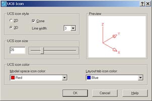 One of the first things to remember is that the only setting for the UCS icon that is constant across all drawings are those that are set in the UCS Icon dialog box which is accessed via the Properties option. All other options are per drawing. In the UCS Icon dialog box you can specify the icon graphic, its width size and color. You also have an option for the color in Model and Paper space.
[ON/OFF/Noorigin/ORigin/Properties]
Other things to consider with the UCS icon:
- To force the UCS icon down into the lower left corner, use the Noorigin option.
- If you don't work in a vacuum, remember that any drawing you open, whether it originates from within your company or not, may have a unique UCS position.
- When you reposition the UCS Origin (as in Step 3 of the lead article this month), remember that the icon will not anchor to the origin unless the UCSICON option of ORigin has been specified. (Or set via the lengthy process from the View menu).
 |
 |
Note: If the UCS icon does not anchor to the UCS origin, it is probably because the graphic of the icon itself cannot be completely displayed based upon the position of the UCS origin within the display. Pan your drawing and the icon will probably re-appear on the Origin.
Donate to CADTutor
If you found this article useful, you might like to consider making a donation. All content on this site is provided free of charge and we hope to keep it that way. However, running a site like CADTutor does cost money and you can help to improve the service and to guarantee its future by donating a small amount. We guess that you probably wouldn't miss $5.00 but it would make all the difference to us.
Note from Michael: I want to thank all of my customers for continuing to retain my training services (some for over three decades!) and let you know your donations do not go to me personally, but to the ongoing maintenance of the CADTutor ship as a whole and to support the yeoman efforts of my friend and CADTutor captain, David Watson, to whom I am grateful for this monthly opportunity to share a few AutoCAD insights.
Share this page:


The Basics
- Dual Dimensions in a Dim…
- UCSICON Options
- "Best of" Basics: Irreg…
- Tool Palette Basics
- Original Dimension Value
- Possible Solutions to th…
- Avoid Using 'Standard' i…
- Shorten the Plot Scales…
- Update the Source File B…
- User Increment Angles fo…
- Drawing Information
- 'Sign Language'
- Rotate with the Copy Opt…
- Use the INSERT Osnap on…
- To or From the Current L…


