

 Michael’s Corner #93
September 2010
The Clever & The Curious
Getting from Point A to Point B is not always a straight line in AutoCAD and we occasionally need to get very clever in our efforts and frequently discover some curious behavior. Such was the case in recent customer visits and seminars which have lead me to this month's collection where you learn how to…
…Update all instances of a block in a drawing after the tool palette block definition has been modified.
…Incorporate Otrack with Direct Distance entry.
…Re-order the attribute order when creating attributed blocks.
…Float and manipulate a Panel from the Ribbon.
Autodesk University registration opens up this month, too [September 14 for AU in Las Vegas and Virtual and September 28 for AU Extension]. My seminar, The AutoCAD Toolbelt II: Customizing and Power Tools for Productivity, will be on Tuesday, November 30, from 2:00 – 3:00. If you're going to AU, come to my session and sit in the front row!
And if you have yet to do so, you can order The AutoCAD Workbench from my website using PayPal or download the order form.
Hope you all had a great summer!
If you would like to contact me directly, you can do that also.
Blessings to one and all,
Michael
Updating a Block Definition in a Drawing [Block from the Palette]
 It would be patently foolish (read "stupid") of me to ever claim I know everything about this endless product called AutoCAD. I don't. As a matter of fact, when I was presenting an AutoCAD Toolbelt seminar for several dozen designers at Metrocon10 in Dallas last month, my mind went blank when asked by one of the attendees – right there in the front row, no less – how I would resolve the dilemma. More attendees to the rescue!
The Problem
You placed numerous references of the Widget block from your tool palette into Drawing ABC.
Now you change the Widget block in its Source drawing (the drawing from which the tool palette pulls the Widget block).
You go to place the newly updated Widget block from the tool palette into Drawing ABC… but the drawing only acknowledges the old one.
The Question
 How do you tell Drawing ABC, "Use this newly updated Widget block coming from the palette"?
The Answer
You need to Redefine the Widget block in Drawing ABC.
Of course, if you are currently in Drawing ABC when you change the definition of the Widget block using the Block Definition dialog box, AutoCAD will prompt you to Redefine the block.
If, however, you are not redefining the block geometry in the same drawing, but simply introducing a block with the same name, AutoCAD will use the block that is already in the drawing with that name.
 AutoCAD can only "compare" block definitions and prompt you regarding the redefinition of the block if you are inserting a .DWG with the same name as an existing block definition.
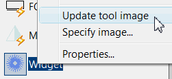 Note: After changing the block in your Source drawing, right-click on the block on your palette, then click Update Tool Image to see the new ‘look’ of your block. (see Michael's Corner, March 2006, on the importance of the Block Source File of blocks on a tool palette. You will also find this on p. 180 of The AutoCAD Workbench.)
The Solution
You will need to use the Wblock command (Write Block) to create a Widget.dwg from the Widget block, then insert it into Drawing ABC. The Wblock command was covered in Michael's Corner, June 2006 (or p. 79 in The AutoCAD Workbench).
The following solution continues where the proposed scenario in the above ‘Problem’ leaves off
.How to Update the Definition of a Block in a Drawing
 Open the Block Source drawing containing the hypothetical Widget block from ‘The Problem’ scenario above.
Launch the Wblock command by typing W to open the Write Block dialog box.
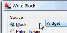
Click the radio button for Block, then select Widget from the list of block names currently in your block source drawing.
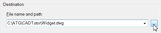
At the bottom, under Destination, you will notice that Widget.dwg has been specified as the file name (the point of the exercise), but you will probably want to specify a path.
 Click OK to create the Widget.dwg in the specified path.
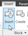
Return to the hypothetical Drawing ABC in ‘The Problem’ scenario above, then launch the Insert command [Insert tab
 Block panelInsert].
In the Insert dialog box, click Browse, then navigate to where you saved Widget.dwg, select it, then click Open to return to the Insert dialog box.
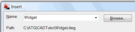
Click OK and you will see the alert regarding the Widget block definition.
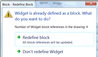
Click Redefine Block.
At this point, all instances of the Widget block in Drawing ABC will look like the Widget block on the tool palette! Phew!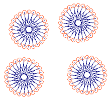
Power Tool
Otrack with Direct Distance Entry
I was training my buddy Tommy at the Corning plant in Harrodsburg, and I was showing him the Extension object snap feature (see Michael's Corner, July 2003 or p. 64 in your copy of The AutoCAD Workbench). I explained the Extension feature acquires the angle of a line, then enables you to place points that ‘extend’ beyond the endpoint of that line… but then I got to thinking: Can we use Otrack to specify a distance from an object?
Object Snap Tracking was covered in Michael's Corner, September 2007 (p. 37 in The AutoCAD Workbench), but only in the context of tracking from the endpoints of two separate objects and where they intersect. Check this out!
How to Use Otrack with Direct Distance Entry
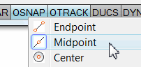 Set your Osnap to Midpoint, turn on Osnap, and turn on Otrack.
Launch the Circle command
Position your cursor at the midpoint of a line, but DON'T CLICK; AutoCAD just needs to ‘acquire’ that location.
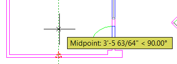 Now move perpendicularly (yes, that's a word) away from the line, and you will see a dashed line along with a tooltip, as shown here. That's the Otrack feature doing it's "tracking" thing.
Enter 48 as the distance away from the line you would like to place the center of the circle. AutoCAD will begin the circle exactly 48″ away from the acquired midpoint!
The Odd Spot
Attribute Definition Order
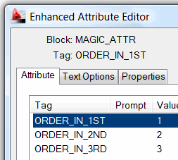
 If you have ever created an attributed block, you may have noticed that when the block is inserted, the order of the attributes is the exact opposite of the order in which they were added. This sounds weird, but here's what I found at my customer site one time.
If you are unfamiliar with how to create an attributed block, see Michael's Corner, June 2003 (The AutoCAD Workbench, p. 121).
How to Re-Order Your Attribute Order
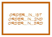
 Using Define Attributes [Insert tabAttributes panel], create attributes in the order you want them to be seen in the drawing, per the first illustration.
Create the block using the Block command [Insert tab
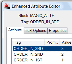
Block panelCreate].After the block has been created, double-click on it to view the attributes… and they're probably in the reverse order, as shown in the second illustration.
Here's the fix…
Explode the block.
 Go back through the process to re-create the block – use the same name, re-select the objects, specify the same base point. When prompted, click Redefine the Block.
Now double-click on the block to view the attributes… and they're in the right order!
Craziest thing I've ever seen… but then, consider the source.
The Basics
Floating a Panel from the Ribbon
 With the first introduction of the Ribbon in AutoCAD 2009, you have been able to drag a panel from the Ribbon and allow it to float in the drawing area. Application?
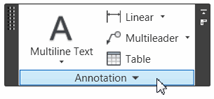
Let's say you will be spending most of your day annotating a drawing primarily with text, dimensions, and leaders. Rather than leaving the Ribbon open, drag off the Annotation panel from the Home tab (shown here), then minimize the Ribbon.
Insights on the Floating Panel
 On the Home tab, for example, click on the Annotation panel title, then drag it down and release it in the drawing area.
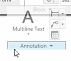
When you hover over any element of the now-floating panel, ‘handles’ will appear on the left and right sides as shown in the first illustration. Use those handles to reposition the panel in the drawing area.
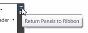 When the time comes, at the top of the right-side handle is a button to Return Panels to Ribbon.
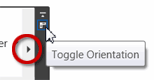 The Toggle Orientation button refers to the position of the black triangle for the panels with expanded groups of tools.
See the Ribbon Basics tutorial for more details on working with panels and the ribbon.
Left Field
Your Laptop Screen:
Corning is a pretty significant player in the glass market – specifically the market of the extremely thin glass that's quite possibly between your face and this website this very moment. The reason I mention this? You probably never imagined that those particular products… are made at the Corning plant about an hour down the road from me in Harrodsburg, KY.
Donate to CADTutor
If you found this article useful, you might like to consider making a donation. All content on this site is provided free of charge and we hope to keep it that way. However, running a site like CADTutor does cost money and you can help to improve the service and to guarantee its future by donating a small amount. We guess that you probably wouldn't miss $5.00 but it would make all the difference to us.
Note from Michael: I want to thank all of my customers for continuing to retain my training services (some for over three decades!) and let you know your donations do not go to me personally, but to the ongoing maintenance of the CADTutor ship as a whole and to support the yeoman efforts of my friend and CADTutor captain, David Watson, to whom I am grateful for this monthly opportunity to share a few AutoCAD insights.
Share this page:


The Basics
- Dual Dimensions in a Dim…
- UCSICON Options
- "Best of" Basics: Irreg…
- Tool Palette Basics
- Original Dimension Value
- Possible Solutions to th…
- Avoid Using 'Standard' i…
- Shorten the Plot Scales…
- Update the Source File B…
- User Increment Angles fo…
- Drawing Information
- 'Sign Language'
- Rotate with the Copy Opt…
- Use the INSERT Osnap on…
- To or From the Current L…


