

 Michael’s Corner #91
July 2010
July Celebrations!
Happy 234th birthday, USA! (Well, we have to celebrate something since it won't be a soccer trophy!)
 I had another totally great time in Guam again last month! Here's my team of students from the AutoCAD 2010 Update course I presented for New Horizons Computer Learning Center.
As many of you know, my training sessions are fertile ground for new articles and Guam was no exception. We were all lamenting about the "exploded box" icon for Explode that was introduced in AutoCAD 2009, so I told the guys I would show 'em how to put the firecracker back on the Explode button.
Here's what's in store for July 2010:
…Put the (4th of July) firecracker back on the Explode button
…Including ‘Prompt for Rotate’ in Dynamic Block with multiple insertion points
…‘Single’ option for Copy
…Multiple Points in the Distance option of Measuregeom
And if you have yet to do so, you can order The AutoCAD Workbench from my website using PayPal or download the order form.
If you would like to contact me directly, you can do that also.
Blessings to one and all,
Michael
Put the Firecracker Back on Explode!
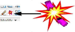 I figured the American Independence Day celebration on the 4th of July would serve as a perfect opportunity to review how you can put the firecracker/dynamite back on the ‘Explode’ button. Just be sure to Export the one that's already there in case you blow it (pun intended), and want to put the ‘exploded box’ back.
This will involve opening the CUI, so if you have made any changes to your Ribbon/Panel arrangement, be sure to use Save Current As from Workspace Switching (see: How To Update Your Workspace, p. 2 in The AutoCAD Workbench).
Geek note: You will soon discover that the ..\Icons folder does not contain any .BMP files. There is, however, a certain level of complexity that you must go to in order to do exactly what Autodesk does for button images on the Ribbon. I also found that… "Bitmaps are stored in AcadBtn.xmx as custom resources which are in fact .ICO files (icons)"… but I'm not going there in this example.
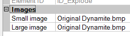
Prerequisite: Before you start this exercise, you may want to go to my website and download the suggested .BMP files that you will find at the bottom of that page under CADTutor Files. Please notice the suggestion that you put them in the ..\Support folder of your AutoCAD. One of the files you find there can be the replacement for the current ‘Exploded Box’ icon.
How to Add a Button Top to a Tool on the Ribbon
Open the CUI.
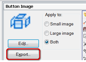
On the left, under Commands, navigate to the Explode command, then click on it to display the Button Image panel in the upper right.
To backup the current image, click Export to open the Export Image File dialog box that defaults to the (very deep) ..\Icons folder.
Under Appearance, click the Button Style item, then click the dropdown to display the four options.
Enter a name for the .BMP, such as Exploded_Box, then click Save.
To put a different .BMP image on that button, click Edit to open the Button Editor dialog box.
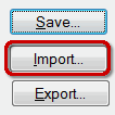 Click Import, then navigate to the location where you saved the .BMP files from my website (hopefully in the recommended ..\Support folder).
Select the image file you would like to use for the button top, then click Open.
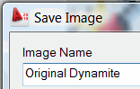 To complete the procedure, click Save to open the Save Image dialog box where you can enter the name of the button top, then click OK.
Note: Notice that the Save Image dialog box has no ‘Browse’ button; my suspicion is that it is incorporated into the AcadBtn.xmx mentioned in the ‘Geek Note’, above. You will also notice the name given is displayed in the Properties panel for the Explode command.

 Click OK to close the Customize User Interface and save your changes… and then you'll see your new Explode button!
Power Tool
‘Prompt for Rotate’ in Dynamic Blocks with Multiple Insertion Points
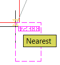 With multiple Insertion Points on a Dynamic Block, you can use the Ctrl key to cycle to the desired insertion point, then place the block as needed (The AutoCAD Workbench, p. 89 or Michael's Corner, November 2005). The literal ‘Catch 22’, is that each insertion point is manifested by an alignment parameter which incorporates the object snap called ‘Nearest’.
The problem comes when you're placing this dynamic block on a corner and the alignment parameter acquires the other line and flips that thing around. I find this most often when I also have Endpoint on as an object snap. Very aggravating.
Solution
![]() In the Tool Properties dialog box for that block, set the Prompt for Rotation to <Yes>. Now, if it misbehaves and will not perform the proper ‘alignment’, at least you have positioned it with the desired insertion point and can now rotate it into position!
In the Tool Properties dialog box for that block, set the Prompt for Rotation to <Yes>. Now, if it misbehaves and will not perform the proper ‘alignment’, at least you have positioned it with the desired insertion point and can now rotate it into position!
The Odd Spot
"Single" Option for Copy
When we (finally) got the Copy command to be in ‘Multiple’ mode by default, I'm sure many of you shared in my celebration of something that was very long in coming. However, some did not find it to be the optimum condition. And although I don't hear it very often, I can understand how the "Single" mode may be the preferred condition.
Just in case you would like to check it out, here are the options you'll want when you run the Copy command:
Command: COPY
Select objects: 1 found
Select objects: [ENTER]
Current settings:  Copy mode = Multiple
Specify base point or [Displacement/mOde] <Displacement>: O
Enter a copy mode option [Single/Multiple] <Multiple>: S
Specify base point or [Displacement/mOde/Multiple] <Displacement>: [Pick a point]
Specify second point or <use first point as displacement>: [Pick a point]
Command:
The COPYMODE variable
Although you can change the copy mode on the fly as in the command sequence above, some of you may want to set "Single" mode to be the default. To do that, simply set the COPYMODE variable to 1.
Command: copymode
Enter new value for COPYMODE <0>: 1
Command:
You can change the default back to "Multiple" at any time by setting the variable back to 0.
The Basics
‘Multiple Points’ Option for Measuregeom Distance
 Training in the Bay Area today I saw another common routine among AutoCAD users that I would really like to eliminate from "standard operating procedure". Specifically, using the Linear (or Aligned) Dimension command to find the distance between two points.
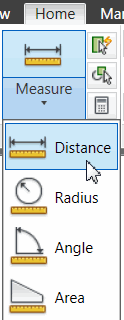
Alternatives? The Distance command (old school, but functional) or the Distance option of the Measuregeom command (introduced in AutoCAD 2010). On the Home tab![]() Utilities panel, you will see a collection of commands under the ‘Measure’ label. Those features are the options for Measuregeom.
Utilities panel, you will see a collection of commands under the ‘Measure’ label. Those features are the options for Measuregeom.
Here's how I would recommend as the new "Standard Operation Procedure" to find distances between points. [The AutoCAD Workbench, p. 58]
How to Find the Distance Between Multiple Points
Create a new layer named Electrical, give it a color, then set it to be current.
-
Zoom up to the area of a drawing where you want to find the distance between points, then click Distance [Home tab
 Utilities panel] and you see the following prompt:
Command: _MEASUREGEOM
Enter an option [Distance/Radius/Angle/ARea/Volume] <Distance>: _distance
Specify first point:
-
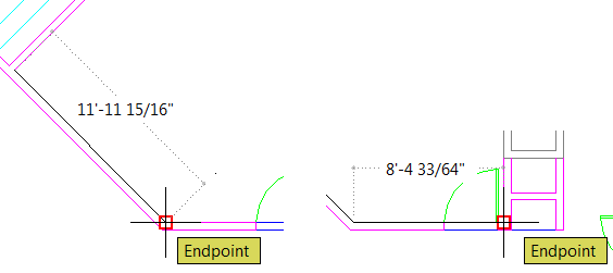
Pick a point to begin the inquiry, then move and just hover over the next endpoint for the distance to see a dynamic dimension between the two points… and you've only specified one point so far!
After specifying the first point, you now see the following prompt:
Specify second point or [Multiple points]:
-
Enter M for the Multiple points option. When you pick the second point, the distance resets to 0, and now you can hover over the next endpoint for the dimension.
When you pick a point, the distance resets and you can continue around the drawing identifying the distances.
I think you will find that a bit more expedient in finding the distances you're looking for.
Left Field
About the Ernest Orlando Lawrence Berkeley National Laboratory:
 The Lab's legacy began in the summer of 1928, when a 27-year-old physics professor named Ernest O. Lawrence was wooed from his faculty position at Yale University to a job at the University of California's Berkeley campus. While at Berkeley, Lawrence invented a unique particle accelerator called a cyclotron which would prove his hypothesis: whirling charged particles around to boost their energies, then casting them toward a target is an effective way to smash open atomic nuclei. The cyclotron would go on to win Lawrence the 1939 Nobel Prize in physics and usher in a new era in the study of subatomic particles.
And it is my distinct pleasure to count the Lab’s Director of Facilities a dear friend, along with the many AutoCAD users I have trained there over the last few years. -Michael
Donate to CADTutor
If you found this article useful, you might like to consider making a donation. All content on this site is provided free of charge and we hope to keep it that way. However, running a site like CADTutor does cost money and you can help to improve the service and to guarantee its future by donating a small amount. We guess that you probably wouldn't miss $5.00 but it would make all the difference to us.
Note from Michael: I want to thank all of my customers for continuing to retain my training services (some for over three decades!) and let you know your donations do not go to me personally, but to the ongoing maintenance of the CADTutor ship as a whole and to support the yeoman efforts of my friend and CADTutor captain, David Watson, to whom I am grateful for this monthly opportunity to share a few AutoCAD insights.
Share this page:


The Basics
- Dual Dimensions in a Dim…
- UCSICON Options
- "Best of" Basics: Irreg…
- Tool Palette Basics
- Original Dimension Value
- Possible Solutions to th…
- Avoid Using 'Standard' i…
- Shorten the Plot Scales…
- Update the Source File B…
- User Increment Angles fo…
- Drawing Information
- 'Sign Language'
- Rotate with the Copy Opt…
- Use the INSERT Osnap on…
- To or From the Current L…


