

 Michael’s Corner #7
July 2003
Extractions and Odd Angles
Continuing from last month's column on assigning attributes to blocks, this month Michael reviews the Attribute Extract feature that has superceded the need to make your own attribute template file. You also will discover where Autodesk hid the Group toggle feature as well as how to more effectively edit and work in drawings that have odd angles. In the Basics this month you will gain some insight into the One-Two punch of subdividing linework with Point objects.
If you would like to contact me directly, you can do that also.
Blessings to one and all,
Michael
Extracting Attribute Data
Last month we reviewed the fundamentals of assigning attributes to a block and the result when that block is inserted into a drawing. In the event that you would like to tabulate the attribute information of the inserted blocks (i.e., not the information of an attributed title block), that's where the Attribute Extract feature comes into play.
Extracting the Attribute Data
 Buried over at the end of the Modify II toolbar is the Attribute Extract tool. If you have muddled through creating your own attribute template before, this is a Godsend. This tool launches a wizard that steps you through the process for collecting the data. Make your choice for selection, then choose Next and make your choices regarding Xrefs and nested blocks, then Next.
If this is the first time you have used these attributed blocks in a drawing, choose No Template to open the Select Attributes dialog listing the blocks on one side and the attributes on the other. [An attribute template has no bearing upon what you may know as a drawing template; same word - different app.]
Use the Check All/Uncheck All buttons as necessary, then select the blocks and their associated attributes you would like to display in spreadsheet format. Although not listed in the Attributes list, the Block Name will be included in the extraction file by default. Click Next to move on to the View Output dialog. Click Alternate View to see if that arrangement of information is more useable, then Next.
If you will need this configuration again, choose Save Template to create a .blk file so you can select "Use Template" next time. On the final Export page of this wizard, make your selection of File Name, location and File Type for the resulting file. You have a choice of .csv, .txt, .xls or .mdb. The Excel file (.xls) is all formatted and ready to sort by header.
Note: Before you type a name in the File Name box, navigate to the desired folder first.
Attribute-related Commands and Variables
DDATTE - Edit the value of attributed blocks using a dialog.
-ATTEDIT - (Notice the hyphen); edit numerous other attribute conditions.
Double-click the block. In A2002 and A2004, this opens the Enhanced Attribute Editor.
ATTREQ - Set to <1>, you are prompted for the attribute values. If you set ATTREQ to <0>, however, the attributed block goes in with the constant or default values and you can edit them later. This is particularly useful when you just need to get the blocks in the drawing and can't take the time to respond to numerous attribute prompts.
ATTDISP (also set with ATTMODE) - The default value of <Normal> abides by your original visibility setting when creating the attribute itself. Set to <ON>, all attributes are displayed. Set to <OFF> turns off all attribute text.
Power Tool
Extending along Odd Angles
 We will frequently need to work on drawings that are not always perfectly rectangular. Drawings in which there are odd angles. For those occasions, the Extension feature works like a champ (not in LT). If the goal of the exercise is to begin a circle (or rectangle or line or block) at a specific distance from a point and co-linear with an existing line, turn on the Extension feature in the Osnap dialog, as well as Object Snap (F3).
At the prompt for the center of the circle, hover over the point from which the offset will take place to display the Osnap marker, but DON'T PICK here. As you move your cursor away from the object, AutoCAD assesses the angle of the line and indicates a dashed line with the distance and angle in the tooltip box - DON'T PICK here, either. Type the distance along this line and from the initial point for the placement of the center point of the circle (or rectangle or line or block).
The Odd Spot
Group toggle change
Prior to A2002, you could toggle grouping with Ctrl+A. In an effort to be more fully Windows-compliant, Ctrl+A is now Select All. This is not necessarily a bad thing, until you encounter drawings in which the Text Mask feature of the Express Tools has been used. If you move masked text and the mask stayed behind, you could Undo, then toggle on Groups (formerly with Ctrl+A) and do it again. If you need to toggle on and off your groups nowadays, the Pickstyle variable in AutoCAD 2002, oddly, holds the key to the grouping of objects.
A Pickstyle setting of 1 or 3 retains the group association of the masked text's wipeout object to the text. A setting of 0 or 2 disassociates the masked text group and you end up with a hole in your drawing if you move (or delete) the text.
Note: If you have a "mystery spot" in your drawing, use the Wipeout command from the Express Tools and change the Frame option to On, then you can erase the wipeout object.
Bright spot: Ctrl+H is the new official toggle method for groups or associative hatches. Who'dathought.
The Basics
Subdividing Your Linework
 Subdividing a line into a user-specified length or number of divisions is probably not something that is part of your daily drawing regimen, but when you need it, what do you do?
It's a two step process:
A Configure your Point Style, then
B Use Measure or Divide.
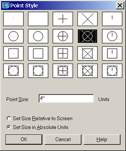
A When subdividing linework, AutoCAD doesn't snip it into bits, it places a point object at the requested intervals. Points can then be snapped to using the Node object snap. To set the point display mode (PDMODE), choose Format/Point Style to open the Point Style dialog box. After making your selection from the group of icons, I would recommend setting the size to the Absolute Units setting then enter the Point size as necessary. For drawings smaller than a breadbox, a size of 0.5 may be a good starting point (pun intended). For larger drawings of the architectural variety, start with 4 and see how it looks.
B-1 To divide your line into a specific number of sections of the same length, use the Divide command (Draw![]() Point
Point![]() Divide). You are prompted to select the object to divide, then the number of segments (or a block name if you don't want to use points). After entering the number of segments, AutoCAD places points at the specified interval.
Divide). You are prompted to select the object to divide, then the number of segments (or a block name if you don't want to use points). After entering the number of segments, AutoCAD places points at the specified interval.
B-2 To place points at a user-specified distance, use the Measure command (Draw![]() Point
Point![]() Measure). After selecting the object to measure, AutoCAD places points along the linework.
Measure). After selecting the object to measure, AutoCAD places points along the linework.
Major Tip: AutoCAD begins the measuring process from the endpoint nearest the pick point of the object selected. This means you will get a different result based upon the location of the pick box when you select the object. In the illustration, I selected the horizontal line on the left side of the line.
Donate to CADTutor
If you found this article useful, you might like to consider making a donation. All content on this site is provided free of charge and we hope to keep it that way. However, running a site like CADTutor does cost money and you can help to improve the service and to guarantee its future by donating a small amount. We guess that you probably wouldn't miss $5.00 but it would make all the difference to us.
Note from Michael: I want to thank all of my customers for continuing to retain my training services (some for over three decades!) and let you know your donations do not go to me personally, but to the ongoing maintenance of the CADTutor ship as a whole and to support the yeoman efforts of my friend and CADTutor captain, David Watson, to whom I am grateful for this monthly opportunity to share a few AutoCAD insights.
Share this page:


The Basics
- Dual Dimensions in a Dim…
- UCSICON Options
- "Best of" Basics: Irreg…
- Tool Palette Basics
- Original Dimension Value
- Possible Solutions to th…
- Avoid Using 'Standard' i…
- Shorten the Plot Scales…
- Update the Source File B…
- User Increment Angles fo…
- Drawing Information
- 'Sign Language'
- Rotate with the Copy Opt…
- Use the INSERT Osnap on…
- To or From the Current L…


