

 Michael’s Corner #106
October 2011
Colorful Settings
Not quite sure how I ended up with 3 out of 4 articles involving color, but that's how it turned out. I then discovered that I had not been specific about the type of text object that works best with a Dynamic Block (covered in Michael's Corner, August 2011), so I covered the creating of an attribute so the Dynamic Block will be a wee bit more effective.
So, for my birthday month (October 12th, thank you), here's what I have in store:
…Creating a button on the Quick Access Toolbar to load your favorite linetypes automatically
…Follow-up on the stretching Dynamic Block and how to create an Attribute Definition
…The curious case of a transparent Command line
…How to color new dual-element Command line in AutoCAD 2012
I'll be turning in the content for my AutoCAD University labs soon, so stay tuned for the posting of that workbook on my Home page in December.
Hope your October is great!
If you would like to contact me directly, you can do that also.
Blessings to one and all,
Michael
Load Linetypes from the QAT
 Once upon a version, all the Linetypes were loaded into each drawing. Now if you want 'em you have to Load 'em. Of course you can put the ones you want in your template, but here's another way of going about it. The following macro can be put onto a button for the Quick Access Toolbar – as shown below – a palette button, or on your customized Panel.
How to Load Linetypes from a Custom Button on the QAT
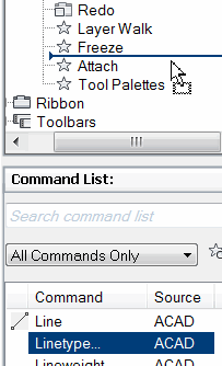
Open the CUI.
In the Command list, drag the Linetype… command up into the list of your QAT content.
Click on the Linetype… command in the QAT, and the Properties for the command are displayed on the right side of the CUI.
For the Macro, enter the following:
'-LINETYPE;LOAD;HIDDEN,PHANTOM;;;
Note: Notice there's a comma between the names of the linetypes being loaded.
Now modify the other Properties to something like you see in the image shown.
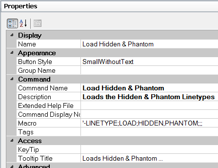
To assign a button top image, click the Linetype item in the list of QAT commands to make it current.
In the collection of images, click anything (seriously), just so you can enable the Edit button.
Click Edit to open the Button Editor, then check the box for Grid.
Click one of the default colors, then draw a couple lines similar to the ones shown here.
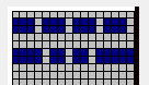 Click Save and enter HIDDEN_PHANTOM in the dialog box as the image name.
The problem I have with that step, is that I have no idea where it's going (I do, but it's generally an uneditable location), so…
Click Export, then navigate to the ..\Sample folder of AutoCAD. Basically, you will want to save your custom image to a location that won't be deleted when you get a new version of AutoCAD or need to reinstall your current version.
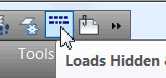 After saving and exporting your work of art, click Close to close the Button Editor. You will notice, under the Command List, that your image is now assigned to Load Hidden & Phantom!
Click OK to apply your changes and close the CUI and you should be good to go!
Power Tool
Follow-Up to Dynamic Block that Stretches (August 2011)
If you tried to make the Dynamic Block that was presented as the lead article in the August 2011 Michael's Corner you were probably successful in making it stretch, but if you used Text or Mtext, you were not prompted to edit the text string, but to open the Block Editor.
 Please forgive my oversight. The very first step in that exercise should have stated that you should create an Attribute Definition as your text, then create the block. Although that was one of the suggested text objects, it should have been the only one.
For those of you unfamiliar with creating an Attribute Definition, here are the steps I used to create the attribute I used for that Dynamic Block.
How to Create an Attribute Definition
Set the desired layer and text style to be current.
On the Insert tab
 Block Definition panel, click Define Attributes to open the Attribute Definition dialog box.
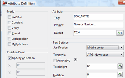
Fill in the Tag, Prompt, and Default fields similar to that shown in this illustration, and set the Justification to Middle Center.
I would recommend you check the box to Specify On-Screen, and the text height should be appropriate for the application.
Click OK after configuring your attribute definition, then place the resulting definition in the drawing.
 At this point, you can continue on with the steps to create the Dynamic Block that stretches found in August 2011.
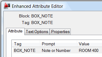
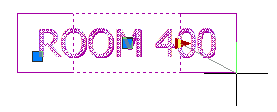
Once you place that block, you can single-click on it to adjust the width and/or double-click it to open the Enhanced Attribute Editor where you can change the text!
The Odd Spot
Transparent Command Line
 Not sure why you'd do this, but then, that's why I call it the Odd Spot… and sometimes I find things that are ‘odder’ than others. In this case, adjusting the Transparency setting of the Command line if you float it in the drawing.
How to Set the Transparency of a Floating Command Line
On the left edge of the Command line, click on the vertical bar, then drag it into the drawing area. This will result in a floating Command Line window.
Right-click anywhere in the Command line, then click Transparency to open the Transparency dialog box (which can also be used for tool palettes and – curiously – the Properties palette).
Adjust the upper slider for the transparency of the palette, then click OK to close and apply your setting. In this figure, I set the transparency to 60% Opacity.
Now position the Command line over some objects in the drawing and you'll see through the Command line!
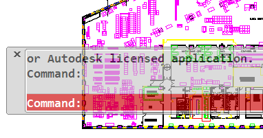
Note: When you approach the Command line with your cursor it becomes more opaque, and when you click in Command line, it becomes completely solid. I welcome any ideas on a practical application for this feature, (unless you figure they did it just because they could!)
The Basics
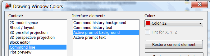
Command Line Color
AutoCAD 2012 enables you to set the color of not only the Command line. More specifically, the color of the Active Prompt Background (and Text) can be set independent of the color for the Command History Background.
How to Set your Command Line Color
Right-click in the Command line, then click Options.
On the Display tab, click Color to open the Drawing Window Colors dialog box shown here.
Under Context, Click Command line, then under Interface Element, click the desired element of the Command line.
Now choose a Color for the selected element. If you gom it up, you can always click Restore Current Element, otherwise, click Apply & Close to see your colors.
Left Field
All by its lonesome… With its own coffee! :
I usually try to dodge training on my birthday, but when my customer in Honolulu asked me to come over while I was traveling in California, I agreed – with approval from my lovely bride, I might add. So I wanted to pass along a couple interesting bits about that 50th state of ours…
A. Hawaii is the most isolated population center on the face of the earth. Hawaii is 2,390 miles from California; 3,850 miles from Japan; 4,900 miles from China; and 5,280 miles from the Philippines, however…
B. It's the only state that grows coffee.
Well, yes, and the scenery is quite lovely, too.
Donate to CADTutor
If you found this article useful, you might like to consider making a donation. All content on this site is provided free of charge and we hope to keep it that way. However, running a site like CADTutor does cost money and you can help to improve the service and to guarantee its future by donating a small amount. We guess that you probably wouldn't miss $5.00 but it would make all the difference to us.
Note from Michael: I want to thank all of my customers for continuing to retain my training services (some for over three decades!) and let you know your donations do not go to me personally, but to the ongoing maintenance of the CADTutor ship as a whole and to support the yeoman efforts of my friend and CADTutor captain, David Watson, to whom I am grateful for this monthly opportunity to share a few AutoCAD insights.
Share this page:


The Basics
- Dual Dimensions in a Dim…
- UCSICON Options
- "Best of" Basics: Irreg…
- Tool Palette Basics
- Original Dimension Value
- Possible Solutions to th…
- Avoid Using 'Standard' i…
- Shorten the Plot Scales…
- Update the Source File B…
- User Increment Angles fo…
- Drawing Information
- 'Sign Language'
- Rotate with the Copy Opt…
- Use the INSERT Osnap on…
- To or From the Current L…


