

 Michael’s Corner #71
November 2008
Actions and Edits
Regardless of the state of the world's economies these days, those of us on the CAD crews still have to be efficient and get the job done. In an effort to support those efforts, I thought I'd take a look at the Action Recorder which can really make repetitive tasks go quickly. I would love to hear how you are using this new A2009 feature, so send me a quick email on the series of commands you're automating.
In the remaining articles, we take a look at an extremely clever use for Alternate Units in a dimension (thank you, Alaska), as well as how to edit the cells in a Table (a question from one of our loyal readers). In the Basics section I am answering a question that typically comes up in training as I'm covering layer states, and that is how to edit a layer state if the layer condition of that state needs to be modified. This was a fun bunch of features to cover.
Wishing all of my fellow Americans a Happy Thanksgiving and may we always remain thankful for the many blessings the good Lord has bestowed upon each one of us.
If you would like to contact me directly, you can do that also.
Blessings to one and all,
Michael
Action Recorder in A2009
![]() This has potential. As you know, I'm a big palette fan and the Action Recorder could easily be a feature that could work hand in hand with the tool palette; albeit with "little brother" status. The Action Recorder is a more user-friendly method of, essentially, creating a batch file or script to run a series of commands.
This has potential. As you know, I'm a big palette fan and the Action Recorder could easily be a feature that could work hand in hand with the tool palette; albeit with "little brother" status. The Action Recorder is a more user-friendly method of, essentially, creating a batch file or script to run a series of commands.
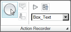 I am also making a concerted effort (OK, maybe it's just a lame effort) to acquaint myself - and as a result, you all - with the Ribbon of AutoCAD 2009. To play along (so to speak), you will find the Action Recorder panel at the left end of the Tools tab of the Ribbon.
In this exercise, I'm going to take the procedure we automated with Custom Button #9 (September 2008) which runs Enclose Text With Object, and show you how to automate the use of that command using the Action Recorder.
Instructions to Create and Play a Simple Macro with the Action Recorder
- Add some random lines of text, such as room numbers or names so you have some text to enclose with objects.
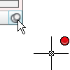
- Click the big, round Record button on the Action Recorder panel which will open the Action Tree. You can close the Action Tree by clicking on the pushpin in the lower right corner. You will also see a red dot beside the cursor which means your every move is being recorded.
- Enter TCIRCLE at the command line to launch the Express feature of Enclose Text With Object.
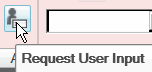
- When prompted to Select Objects, click the Request User Input button on the Action Recorder panel.
- In the resulting alert box which is asking what you want to do, click the first option, Insert a request for input at playback. When the macro is played, it will pause for you to select the objects, then it will continue with the macro.
- Select a few lines of text, then press <Enter> to complete the selection, and press <Enter> again to move on to the next prompt.
When creating macros, you always need to consider the fact that the defaults may be changed the next time the macro is run, so even though you may want to press Enter to accept the default, it's best to enter the desired value, regardless. (I learned this over 20 years ago when rubbing elbows with the programmers of CADVANCE. Email me if you've ever used it, we'll reminisce.)

- When prompted for the offset factor, enter 0.350.
- When prompted for the shape, enter either S for Slots, C for Circles, or R for Rectangles.
- For the last prompt, enter V for Variable.
- Now go up on the Action Recorder panel and click the big, square Stop button.
- Enter a name for this macro (you cannot have spaces in the name), then click OK.
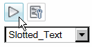
- To run your macro, choose the macro from the list, then click the Play button. For macros containing a Request for User Input, you'll get a (really big) notice box, and you will typically want the option to Provide Input.
Action Recorder Shortcomings: Once an action macro has been recorded, there's no (apparent) method of editing that macro to include some action or command you may have omitted. Also, if the procedure being recorded creates objects (as in the process above), you can record the creating of the layer in the macro, but at the completion of the macro, there isn't a method to restore the previous current layer. This differs from how a button on a tool palette works wherein you can specify the properties of the resulting object(s) - Layer, Linetype, Color, etc. - without changing the current layer.
All told, the potential of the Action Recorder is quite substantial and I have seen applications where it can be used to reset Scale Lists, Purge and Audit drawings, etc. I'll be watching for opportunities to use the Action Recorder and will probably bring those to you as a Power Tool.
Power Tool
Feet & Inches + Inches, Too
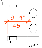 To me, the Alternate Units feature of a dimension style was used to display Metric equivalents of a dimension. But that was before one of my customers in Alaska showed me this amazing tidbit.
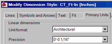
The following process presumes you have created a Dimension Style with the Unit format set to Architectural on the Primary Units tab.
Instructions to Display Ft′-In″ as well as Inches
- Launch the Dimension Style dialog box, then create a New dimension style and click Continue.
- In the New Dimension Style dialog box, click the Alternate Units tab.
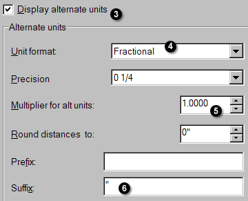
- In the upper left corner, put a check in the box for Display Alternate Units.
- Set the Unit format to Fractional. This will display dimensions in inches only (See Michael's Corner October 2005, Odd Spot).
- The setting for Precision is your call, but then set the Multiplier to 1.00.
- In the Suffix edit box, put the inch marks ( ″ ).
- The last setting you may want to make is to set the Placement feature radio button (under the preview) to Below Primary Value.
The Odd Spot
Copy Table Cell Contents
One of our subscribers emailed me regarding copying cells between tables or within the same table. I hadn't really given that much thought, but in the following exercise, I'll take you through that process. These instructions presume you have a drawing open that has a table in it. In August of this year I dedicated the entire Corner to coverage of Tables in AutoCAD 2009.
Instructions to Copy Table Cell Contents to Other Cells
- Open a drawing containing a Table or create one from scratch and add contents to several of the cells.
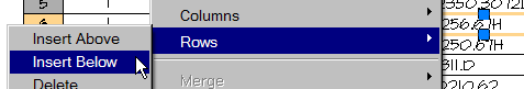
- Click in one of the cells and you see grips on the four sides. Now right-click, then click Rows
 Insert Below . If you have AutoCAD 2007, you will click Insert RowsBelow . (You can also choose Above; your call).
- To copy an entire row, click and drag your cursor within the cells of that row, from one side to the other, to effectively select that content. In A2008 and A2009 the Row and Column headers appear.
- After selecting the contents of the row, right-click, then click Copy.
- Here's where it gets odd: Each of the last three versions of AutoCAD - A2007, A2008, and A2009 - all have different methods of pasting the copied cell contents. Here's how it breaks down…
AutoCAD 2007 - If you selected and copied, say, 7 cells, you will then need to select 7 cells in order to see the Paste option when you right-click.
AutoCAD 2008 - If you selected 7 cells in this version, say, columns A thru G, you must click in cell A of the target row before you right-click and use Paste… because A2008 will allow you to paste the contents pretty much anywhere it has the proper number of cells. I.e., it will populate the table from the cell you initiate the Paste feature.
AutoCAD 2009 - If you selected 7 cells, you will only see the option to Paste if you click in the correct cell in the target row. If you selected columns A thru G to copy, you must initiate the Paste in the A column. It will then populate the cells according to their original Row/Column position.
Note: If you have selected 5 cells in Table XYZ and wish to paste them into Table 123 which has 7 cells, it is advised that you initiate the paste from the leading cell (left most).
The Basics
Updating an Existing Layer State
 Layer states continue to be a popular topic of discussion in my training sessions around the country and I noticed that I have not previously covered how to update an existing layer state in a drawing. If you have, for example, saved a layer state named "Panel Plan" in which only the workstation panels are displayed, and then add electrical components, new layers have been introduced to the drawing and you need to update the Panel Plan layer state to include the duplexes and wire management.
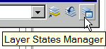
Back in February 2007, I covered Layer States as they were in AutoCAD 2006 and the dialog box has remained unchanged since then, save for the fact that you may now access the Layer States Manager directly from the Layers toolbar, beginning with A2007.
Before beginning the following exercise, open a drawing and save a Layer State (see February 2007 if needed).
Instructions to Update a Layer State
- After saving a layer state for the drawing, turn on additional layers, or add some symbols that introduce new layers to the drawing. In other words, make a modification to the drawing that involves the visibility of layers.
- Launch the Layer States Manager, select the layer state you want to update, then click the Save button.
- You will get an alert box regarding overwriting the selected layer state.
- Click OK to overwrite that layer state and effectively include the newly added layers.

To confirm that your layer state has been saved, change the layer condition by turning on or off some additional layers. Now launch the Layer States Manager and double-click the edited layer state name (which essentially selects and Restores that layer state). If your drawing returns to the condition at which you saved the layer state, it worked!
Left Field
Word Origins - In the 18th century, silhouettes (shadow profiles traced and cut from black paper) were a popular alternative to costly portraits. The word took its name from the French controller general of finance, Etienne de Silhouette. During the Seven Years War against England, he tried to raise revenues by heavily taxing the wealthy. Victims of his high taxes complained and used the word silhouette to refer to their wealth being reduced to a mere shadow of what it once was.
Donate to CADTutor
If you found this article useful, you might like to consider making a donation. All content on this site is provided free of charge and we hope to keep it that way. However, running a site like CADTutor does cost money and you can help to improve the service and to guarantee its future by donating a small amount. We guess that you probably wouldn't miss $5.00 but it would make all the difference to us.
Note from Michael: I want to thank all of my customers for continuing to retain my training services (some for over three decades!) and let you know your donations do not go to me personally, but to the ongoing maintenance of the CADTutor ship as a whole and to support the yeoman efforts of my friend and CADTutor captain, David Watson, to whom I am grateful for this monthly opportunity to share a few AutoCAD insights.
Share this page:


The Basics
- Dual Dimensions in a Dim…
- UCSICON Options
- "Best of" Basics: Irreg…
- Tool Palette Basics
- Original Dimension Value
- Possible Solutions to th…
- Avoid Using 'Standard' i…
- Shorten the Plot Scales…
- Update the Source File B…
- User Increment Angles fo…
- Drawing Information
- 'Sign Language'
- Rotate with the Copy Opt…
- Use the INSERT Osnap on…
- To or From the Current L…


