

 Michael’s Corner #35
November 2005
Autodesk University Ramping Up
Autodesk University (www.autodeskevents.com/au2005) runs from November 28th thru December 1st and should be quite the event. At press time, I had just completed putting together the document for my AutoCAD Toolbelt session which will be held on Monday, November 28th. If I run out of things to say before my 90 minutes is up (right, like that's going to happen), at least I can jump over here and take a look at… the eTransmit feature. It's been around since A2000i and I'm surprised at the number of folks that aren't using it. I was also recently made aware (by a reader) of the "etransmit.txt" file you can make to be used for the transmittal notes. During another investigation recently, I found a way thru the maze that's required to get precision assigned to a table cell in A2006 that contains a summation. And finally, I'm always jazzed when I learn more about the A2006 dynamic blocks. Heidi Hewett (Autodesk's Technical Marketing Manager) had a webcast that I saw after the fact and she did a review on multiple insertion points of a dynamic block. And if you weren't sure about the difference between the backup file and the autosave file, take a run around this month's Basics section. And join AUGI today! www.augi.com
If you would like to contact me directly, you can do that also.
Blessings to one and all,
Michael
eTransmit
First off, if you're not using eTransmit to exchange drawings with your accounts, you should be. For those of you who remember Pack 'n' Go from the old R14 Bonus tools, eTransmit takes that procedure to the next level. Best part: It makes the .ZIP for you!
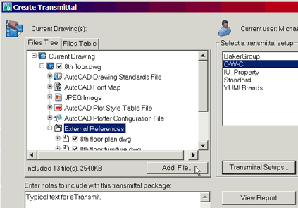
Next, what are the three object types that are NOT included when you send a DWG to someone. Yes, the Xrefs, but also non-native fonts (don't you hate it when you get that font dialog box that can't find Special.shx?!), as well as raster images. One of my students at my recent Iowa State training also mentioned custom linetypes that you may have added to acad.lin. Gold Star!
 Key Features of eTransmit
Files Tree tab: Lists those files which will be included in the transmittal. Deselect those you don't want included.
Files Table tab: Lists the Path / Type / Size / Version / Date of the included files.
Add File button: This is great if you need to include that custom linetype file (LIN) that the recipient may need.
Transmittal Notes box: Put notes in here that you want to have in the body of the email you can automate in the Transmittal Setup dialog box.
Gold Star Tip: This from Paul Wyss, retired PE and evening school educator at the Hilton Head campus of TCLC in South Carolina - "…create a notes file to be to be automatically included with the emailed transmittal of a drawing by creating an ASCII text file called etransmit.txt".
Create the etransmit.txt file in Notepad, then put it in the AutoCAD…\Support folder (under Program Files) and it will automatically appear in the Transmittal Notes box.
View Report: This ASCII text file essentially lists the content of the Files Table tab, along with an explanation of the file types included. The best item in this report, however, is the identification of the Root Drawing if you have included Xrefs.
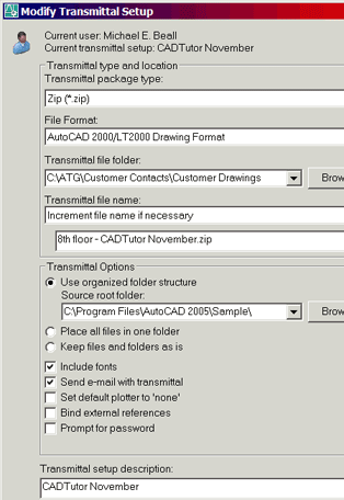
Transmittal Setups: A transmittal setup enables you to create project-specific criteria for the transmittal. For example, you may have one client for which you always have to save down to A2000 format. Or what about those folks who don't really need to keep Xrefs separate and they would just as soon have a single drawing? Solution: Use the setup option to Bind External References.
Setups also enable you to pre-assign a folder for the ZIP, request incremental naming of the file (for ongoing project transmittals), and a number of other options that may be unique to that project.
Power Tool
Dynamic Block Multiple Insertion Points
 This is so excellent! I knew about the ability to assign the Alignment Parameter, but I just learned from Heidi Hewett's webcast that you can have more than one… and toggle between them with the CTRL key!
Although this is my first article on dynamic blocks In these pages, the Alignment Parameter is the easiest to apply and I will have more coverage on dynamic blocks in the months ahead. For additional reading enjoyment, Mark Douglas has a blog called "In the Dynamic Interface" which contains prolific references to dynamic block features. He was very helpful to me as I began my investigation of dynamic blocks in the early days of A2006. [http://mdouglas.blogs.com/in_the_dynamic_interface]
Setup: Start with an existing block. Period. Now you're ready to turn it into a "dynamic block". I'm using a collection of office furniture in the following example.
Instructions to Add an Alignment Parameter to a Block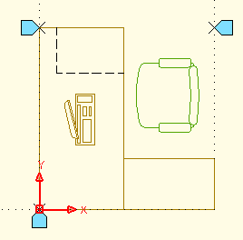
- Double-click the block to open the Edit Block Definition dialog box (displaying your block). Click OK to open the Block Editor. It caught me off-guard the first time I opened it, too, but don't panic, you're still in AutoCAD.
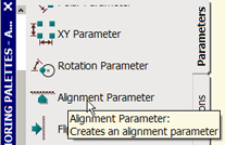
- The Block Authoring palette has three tabs. On the Parameters tab, click Alignment Parameter.
- Pick two points on the block that define a vector to be used as an alignment axis when the block is inserted. A blue alignment icon is added to the first point specified. In the figure, I picked the lower left and lower right corners of the geometry for the first parameter.
- Add at least one more alignment parameter. When you insert the block, you can toggle to these alignment "handles" using the CTRL key.
- Click Close Block Editor and click Yes to save the changes.
- Use the Insert command and select your block. Before taking the block over to existing geometry, go to an empty area in the drawing and just press the CTRL key to see how you can cycle between the alignment parameters.
Note: When you insert a block with alignment parameters, AutoCAD automatically toggles on the Nearest object snap. That makes sense, but here's the question: Since an alignment parameter is designed to automatically align the block to the geometry it is nearest to, just exactly which side of that geometry does it align to, hmm?
As it turns out, if you approach the geometry from side A, the block will align to one side, if you approach the geometry from side B, the block will make the necessary adjustment to align to the other side. It's pretty cool, but you'll have to play with it to get the feel.
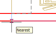 |
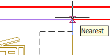 |
- Approach the alignment object (the red line in the figures). In the first figure, you see that the cursor is just slightly below the line and the alignment axis runs the length of the block. In the second figure, the cursor is slightly above the line, causing the block to re-orient to the opposite side. It takes some finessing, but it's very cool.
The Odd Spot
Precision Adjustment for Cells in A2006 Tables
Q: How can I adjust the precision of the cells in a table?
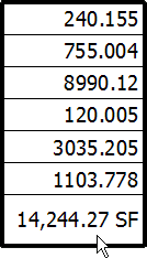
 Maybe you have a spreadsheet of square footages out to three decimal places. When you bring it into AutoCAD, you only need two decimals in the Total.
In AutoCAD 2006 you can assign simple formulas (formulae?) to cells in a table. The key here is to remember that once you have assigned a formula to a cell in an A2006 table, that value is now considered to be a field.
Instructions to Insert Excel Data and Adjust Cell Precision
- In Excel, create a column of numbers out to 3 decimals. Highlight all the cells in that column + one extra one at the bottom , and Copy that column to the Clipboard. [The extra cell is not critical to the process, just useful in this exercise.]
- In AutoCAD, go to Edit
 Paste SpecialAutoCAD Entities.
 - Click to place the column of cells, then press Esc to cancel the editor for the top cell.
- Single click in the bottom, empty cell (this will display the four grips of that cell), then right-click and click Insert Field to open the Field dialog box.
- In the Field Names list, click Formula.
- Click the Sum button and you are then prompted to (essentially) window the cells for the calculation of the sum. Pick the first corner of the window in the top cell, then pick the second corner of the window in the last numbered cell (you don't "go around" the cells like you would when selecting objects).
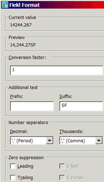
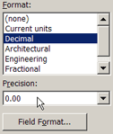
- In the Field dialog box in the Format list, click Decimal. Change the Precision to 0.00 (keeping in mind we had three decimal place in our original Excel values).
- Click the Field Format button to open the dialog box. Make the following changes (as shown in the figure).
Suffix: [space] SF
Thousands: ',' (Comma)
- Click OK, then click OK to close the Field dialog box and see your precision adjusted summation field!
The Basics
AutoSave, Backup, & Drawing Recovery
AutoCAD really does keep you covered, but you have to know where to find your recovery files. And in AutoCAD 2006, there is now a Drawing Recovery Manager to help you find them. First, a point of understanding: The .BAK and the .SV$ are .DWG files, they just have unique file extensions.
The BAK - This file is created as soon as you save the .DWG for the second time and it lives in the same folder as the .DWG. However, if you open an existing drawing, work on it for an hour or so without saving every now and then… and the power goes out, the .BAK is no help because it's just as old as the .DWG.
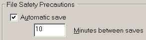 The SV$ - That's the extension for the file that is automatically saved (not AC$), and it's a bit elusive (which is probably what caused Autodesk to come up with the new Drawing Recovery Manager). In the Options dialog box on the Open And Save tab, you probably know of the 'Minutes Between Saves' edit box. It used to be set to three days (OK, it was 120 minutes but it might as well have been three days). Since about A2002 the default time is 10 minutes.
 The question most folks have is where the automatically saved file is saved and what to look for when you get there. In the Options dialog box, on the Files tab about half way down you will see Automatic Save File Location. By default, it is someplace in Documents and Settings (which is getting to be a dumpster, if you ask me), and I think it would be much better suited in a specifically named folder on the C: drive such as \AutoSave. I have mine in C:\Temp. Either way, put it where it will be easy to get to. Especially if you don't have AutoCAD 2006 yet.
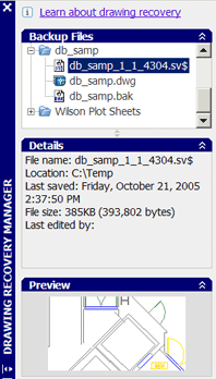 A2006 Drawing Recovery Manager - Let's say you have several drawings open when the power goes out. When the power is restored and you go back into AutoCAD 2006, this palletized interface displays the names of the files you had open at the time of the crash, along with all their family members (BAK & SV$), if they exist.
Under Backup Files, click on a filename to display the file detail along with a preview. To open the file, double-click it. At least this way you don't have to chase down your BAK or SV$ recovery files.
Scenario for Recovery (in A2005 and earlier)
- After power is restored to your system, if you're not sure which recovery file is more current, navigate to the respective folders containing the BAK and SV$ to identify the one you wish to recover to a DWG file.
- In Windows Explorer, click the file you want to rename, hit the F2 key to open the edit box for the file, then rename the file to include the DWG extension. That'll do ya!
Left Field
Equine Curiosity Horses can only breathe through their nose… and can't burp.
Donate to CADTutor
If you found this article useful, you might like to consider making a donation. All content on this site is provided free of charge and we hope to keep it that way. However, running a site like CADTutor does cost money and you can help to improve the service and to guarantee its future by donating a small amount. We guess that you probably wouldn't miss $5.00 but it would make all the difference to us.
Note from Michael: I want to thank all of my customers for continuing to retain my training services (some for over three decades!) and let you know your donations do not go to me personally, but to the ongoing maintenance of the CADTutor ship as a whole and to support the yeoman efforts of my friend and CADTutor captain, David Watson, to whom I am grateful for this monthly opportunity to share a few AutoCAD insights.
Share this page:


The Basics
- Dual Dimensions in a Dim…
- UCSICON Options
- "Best of" Basics: Irreg…
- Tool Palette Basics
- Original Dimension Value
- Possible Solutions to th…
- Avoid Using 'Standard' i…
- Shorten the Plot Scales…
- Update the Source File B…
- User Increment Angles fo…
- Drawing Information
- 'Sign Language'
- Rotate with the Copy Opt…
- Use the INSERT Osnap on…
- To or From the Current L…


