

 Michael’s Corner #88
April 2010
AutoCAD® 2011 Hot Spots
Of the dozens of software titles produced by Autodesk, I am quite delighted to be fluent exclusively on the flagship of AutoCAD®. The first version I trained on was Release 10… which was also the first version in which they thought it would be a good idea to alphabetize the layers. Nice.
Guri Stark, (Vice President, AutoCAD & Platform products) mentioned during our ‘Welcome to the Official Launch of AutoCAD 2011’ session that AutoCAD 2011 is their Silver Anniversary version - their 25th product release. From where I sit, it's another fabulous release and has several features that my primary customer base - contract furniture dealerships and corporate Facility Planning departments - will find extremely helpful. My ‘Top Three’ that I'm presenting this month include:
…An introduction to the Hatch improvements
…The now-intuitive process of polyline editing
…The (hopefully last) revision of the process of selection cycling
Stay tuned, I think AutoCAD 2011 is going to be a great ride.
If you would like to contact me directly, you can do that also.
Blessings to one and all,
Michael
An Introduction to the AutoCAD® 2011 Hatch Updates
Absolutely striking. That was my initial thought when I positioned my cursor over the area to hatch… and a dynamic preview appeared in the area before I even clicked!
Add to that the new contextual tab, and hatches are a whole new ballgame. I've put the new features in a different color in case you're just looking for the new stuff.
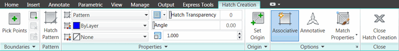
‘Hatch Creation’ Tab Panel Review
Here's a review of the panels you will find on the Hatch Creation tab after launching the Hatch command.
Boundaries
Standard methods of selecting boundaries, Pick Points, Select Boundary Objects. There is an expanded panel containing features for hatch editing.
Pattern
If the hatch type is set to ‘Pattern’ click Hatch Pattern to select from the graphic ‘Ribbon Gallery’ of all hatch patterns.
Properties [START HERE]
This is where you would typically begin configuring your hatch.
Pattern: Hatch type selection: Solid, Gradient, Pattern, User Defined
Color: Pick a color for the hatch, although I always recommend ByLayer
Background Color: You can now specify a background color that is, essentially, a Solid hatch with your pattern.
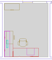
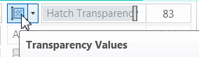 Hatch Transparency: Adjust the transparency of the hatch color. In this image, the color of the hatch layer was black and I used a Solid pattern with a transparency value of 83.
Angle: Use the slider or enter a value for the hatch
Spacing/Scale: Specify the Spacing for a User-defined hatch or the Scale for a Pattern.
![]() Double: The expanded Properties panel contains the option for Double.
Double: The expanded Properties panel contains the option for Double.
Origin
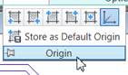 The expanded Origin panel contains icons for the 6 selectable options. If you click Set Origin (the primary option for that panel), then specify an origin for the hatch, the dynamic preview immediately updates the hatch position. Very nice.
Options
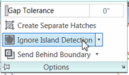 The expanded Options panel provides settings for features shown here. To apply a hatch in an area with furniture or equipment, set the Island Detection value to Ignore Island Detection. Use Create Separate Hatches to maintain independence of each hatch object. The tiny arrow in the lower right corner opens the Hatch and Gradient dialog box from previous versions.
Dynamic Preview
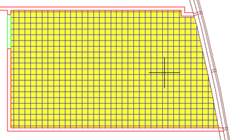 After specifying your hatch parameters, when you position your cursor in the area to be hatched, a preview of the hatch is automatic, by default. Very cool! The hatch in this figure has a background color applied.
Important Note: If the objects bounding the hatch have a Thickness, the Dynamic Preview feature will not work. This may be the case with drawings from architects who have created 3D walls, but receive the drawing in plan view. The preview feature works great as long as the Thickness (or Z-value) of the bounding objects are 0″.
Placing the Hatch
With the dynamic preview feature on, as you are specifying the parameters of your hatch, the command line is just waiting for you with the prompt shown here:
Pick internal point or [Select objects/seTtings]:
Once you click in the area to be hatched (having seen the preview of the result), you then get the following series of responses at the command line:
Selecting everything...
Selecting everything visible...
Analyzing the selected data...
Analyzing internal islands...
Pick internal point or [Select objects/seTtings]:
Curiously, you still have the final prompt to ‘Pick internal point’. You will need to either right-click, press [Enter], or even Esc to accept the hatch placement.
Variables of Note
HPDLGMODE <2>
The default value of 2 for the ‘Hatch Parameter Dialog Mode’ means you get the contextual Hatch Creation tab when you launch the Hatch command. To use the Hatch command the way it was in previous versions, set it to <1>… but at least play with the Ribbon features before you set it back to the old way.
HPQUICKPREVIEW <ON>
Depending upon a myriad of conditions - size of drawing, speed of CPU, source of the drawing, complexity of the area being hatched, yadayada - you may find this feature to be helpful, or not so much. Your call. You will have to enter this setting manually because I didn't see a setting on either the Ribbon or the dialog box.
Power Tool
Polyline Edits in A2011
 Twenty+ years in the making, we now have a stellar procedure for modifying Polylines. As is often the case, Autodesk went the extra 5,280 feet and included some additional features to enhance the initially intended solution.
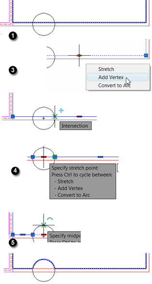
In the following exercise, I have created a polyline inside a room, but failed to accommodate the column. Using the new features of Add Vertex and Convert to Arc, the edits to this polyline take less than 30 seconds!
How to Insert a Vertex in a Polyline in AutoCAD 2011
Click on the polyline of interest and you will see multi-functional grips (they look like a bold minus sign) between each of the corner grips.
Hover in the multi-functional grip on the segment where you want to add a vertex, and you will see a shortcut menu.
Click Add Vertex.
In this exercise, I positioned a new vertex on the right edge of the circle where it intersects the wall. I also added another vertex at the left edge intersection with the circle.
Note: If you mistakenly select the wrong editing feature, when you pause in your editing, you will see the notice to ‘Press Ctrl to cycle between’ the other options. Very clean.
For the arc, I tested the Ctrl feature to cycle through the other options, then placed the arc at the top of the circle to complete the edit of the polyline.
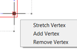 Note: There is also a new shortcut menu when you hover on a regular grip.
The Odd Spot
Diameter-specified Circle with DYN
 Occasionally I'll be a couple steps in to an exercise in a training class and think to myself, "is this the best way to do this&h and is this what I remember doing?"
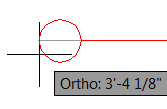
That's exactly where I found myself while training in Guam last month, when I was answering a question regarding creating a 2Point circle. In the upper illustration, after picking the first point at the end of the line - and turning on Ortho - the position of the second point was not held at an orthogonal angle.
How to Specify the Diameter of a Circle Using 2Point
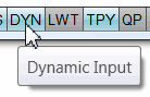 Confirm the Dynamic Input feature is on at the Status bar, then launch the Circle command.
Enter 2P for the 2Point option (or select if from the options list).
 Pick the first point, then confirm that Ortho is on and move your cursor away from the first point to confirm that the diameter line is being held to an orthogonal angle.
Complete the creation of the circle as desired by clicking or entering a value for the dimension.
Note: Curiously, after you have moved the cursor away from the first point, you can toggle Off the dynamic input feature… and the orthogonal placement of the diameter line will hold steady.
The Basics
Object Selection Cycling in A2011
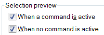 Note: This is one of many circumstances when the ‘Selection Preview’ feature is quite useful. I highly recommend you keep the default settings for this feature, per the checks shown in this box found on the Selections tab of the Options dialog box [Application menu
![]() Options].
Options].
AutoCAD 2011
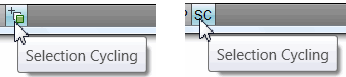
AutoCAD 2011 improved upon the Selection Cycling feature that can now be toggled on from the Status bar. If you're using the icons, it's the last one in line. If you have disabled the icons, you will see SC.
How to Cycle Through Stacked Objects with AutoCAD 2011
 Open a drawing that you know has an overlapping line condition, then launch the desired edit command (this only works with editing commands - such as Move, Erase, etc. - where a pickbox will appear).
Launch any editing command - Move, Copy, Erase, etc. - then click Selection Cycling on the Status bar.
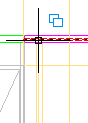
When prompted to ‘Select Objects’, position your cursor over a location where you know the lines overlap. A double-box icon will be displayed above your cursor which, essentially, confirms that more than one line lies below the cursor position.
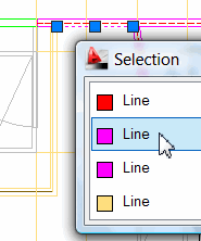 When you click that location, the Selection dialog box appears, listing the object types that share that location, along with their color.
Position your cursor over an item in the list and the associated object highlights in the drawing.
To select the highlighted object, click the item in the list and the Selection dialog box closes.
This is the most elegant idea for this process they have had to date.
Left Field
AutoCAD LT Wins! - Many of us in the audience at the official launch of AutoCAD 2011 were surprised to hear that AutoCAD LT is Autodesk's largest selling product… and it's far from "Light" (the LT actually stood for LapTop when originally launched over 10 years ago now). My friend, Kate Morrical (Technical Marketing Manager for AutoCAD LT) told us of AutoCAD LT's popularity as she was presenting the improvements to the AutoCAD LT 2011 product, of which there are many. Clearly a product recognized for its power at an attractive price point.
Donate to CADTutor
If you found this article useful, you might like to consider making a donation. All content on this site is provided free of charge and we hope to keep it that way. However, running a site like CADTutor does cost money and you can help to improve the service and to guarantee its future by donating a small amount. We guess that you probably wouldn't miss $5.00 but it would make all the difference to us.
Note from Michael: I want to thank all of my customers for continuing to retain my training services (some for over three decades!) and let you know your donations do not go to me personally, but to the ongoing maintenance of the CADTutor ship as a whole and to support the yeoman efforts of my friend and CADTutor captain, David Watson, to whom I am grateful for this monthly opportunity to share a few AutoCAD insights.
Share this page:


The Basics
- Dual Dimensions in a Dim…
- UCSICON Options
- "Best of" Basics: Irreg…
- Tool Palette Basics
- Original Dimension Value
- Possible Solutions to th…
- Avoid Using 'Standard' i…
- Shorten the Plot Scales…
- Update the Source File B…
- User Increment Angles fo…
- Drawing Information
- 'Sign Language'
- Rotate with the Copy Opt…
- Use the INSERT Osnap on…
- To or From the Current L…


