

 Michael’s Corner #145
April/May 2016
Four…
There are three more postings of Michael's Corner to come after this one, and I hope each one will kick your productivity a notch. I'll also be including some “Best of” in case you're just now joining us… or forgot all about it.
And now that Autodesk® AutoCAD® 2017 is now out on the streets, you're going to want to run down to your local reseller and get your own personal copy! Oh, if it were only that simple. (Ch-ching!)
So, as you scroll through this post, you will find insights on…
…The AutoCAD 2017 PDF Import command
…Copying nested objects within a block
…“Best of”: The Wipeout object and Irregular Viewport Frames
And for those of you who would like the last 14 years in book form (or PDF), YES, I am currently updating The AutoCAD® Workbench to include 'em all. The AutoCAD Workbench, Final Edition will be updated to A2017 and will, “Lord-willing and the creek don't rise”, be out by early Fall as the last Michael's Corner is posted.
[Ah, and even though my contribution of Michael's Corner is coming to an elegant end, I'll not be retiring anytime soon. My training around the planet will continue. I'm having waaaaay too much fun seeing my friends and customers and meeting new ones.]
Happy Spring!
If you would like to contact me directly, you can do that also.
Blessings to one and all,
Michael
The Big Dog in A2017
 There are some pretty nice features in AutoCAD 2017, but I think my corporate Facilities customers will consider PDF Import to be a lifesaver, since they are frequently on the receiving end of PDF floorplans.
This will just be an introduction to the feature. The command's Help window covers all the details.
Insights
PDFIMPORT can be used on DWGs with PDF Underlays already attached, or the default option is to select a File (PDF) to import.
They have yet to perfect the recognition of text objects. I participated in a Beta review where text was recognized in some cases, and in others it wasn't. Stay tuned.
Once the command is complete, you may want to consider running Delete Duplicate Objects. See Michael's Corner, March 2012.

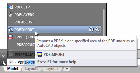
How to Import a PDF File Into the Current Drawing
You can launch this feature from the Insert tab
 PDF Import, or just type it.
Press [Enter] for the File option, then navigate to, and select the PDF, then click Open.
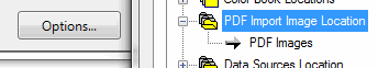
Note: If you have a location where you typically save PDF files, you can specify that path with the Options button at the bottom of the Import PDF dialog box.
The defaults work fine on the half dozen PDF files I tried this on. Here's the Help info on Layers:
Use PDF layers
Creates AutoCAD layers from the layers stored in the PDF file, and applies them to the imported objects. The layer names have a PDF prefix. If no layers are present in the PDF file, object layers are created instead.Create object layers
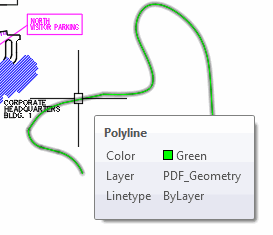
Creates AutoCAD layers for each of the following general types of objects imported from the PDF file: PDF_Geometry, PDF_Solid Fills, PDF_Images, and PDF_Text.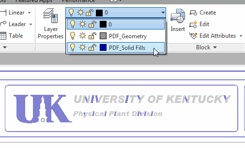
Current layer
Imports all specified PDF objects to the current layer.Note: Keep the box checked for Solid fills. Presently, what appears to be TrueType fonts are, shall we say ‘randomly’ recognized as either fills or Hatch objects. In the image, notice that only certain strokes of the letters are on the PDF_Solid Fills layer.
How to Use PDFIMPORT on a PDF in the Drawing
 You can launch this feature from the Insert tabPDF Import, or just type it.
Select the PDF object and you get the following prompt:
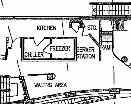
Specify first corner of area to import or [Polygonal/All/Settings] <All>:In this illustration, I created a window around a portion of the attached PDF map. After creating the window, you get the following:
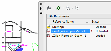
Keep, Detach or Unload PDF underlay? [Keep/Detach/Unload] <Unload>: U

Binding PDF file C:\CTG\CADTutor\ConAgra Campus Map.pdf, page 1 ...
Although it says, “Binding PDF file…” the Unload option technically unloads the referenced PDF and displays the condition in the External Reference Manager. Which means, yes(!), you can Reload that reference if need be.
Bottom Line
This is pretty fantastic. There are some shortcomings in recognizing text objects, but those are being worked on at this very moment. Unfortunately, Scan-to-PDF files are not able to be imported to AutoCAD geometry with this feature, no doubt due to their clarity… or lack thereof.
Other than that, I think it's pretty wonderful that we now get layers, as well as recognition of lines, circles, and arcs.
Power Tool
Copy Nested [Express Tools]
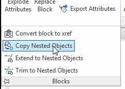 Express Tools have some nice little routines like this Copy Nested Objects [NCOPY].
Insights
Standard COPY procedures apply.
A polyline within a block/Xref retains its polyline definition (i.e., the copy is also a polyline).
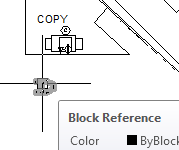
A block within a block/Xref is not retained as a block. Only the selected geometry is copied.
If you want to copy a nested block from within another block, use the Block Editor [Home tab
Block panelEdit] to open the selected block in the Editor, then use Ctrl + C to Copy the nested block. Close the Block Editor, then Ctrl + V to Paste the copied block. Simple but effective.
The Odd Spot
“Best of” Odd Spot: Wipeout
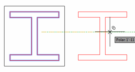
It's very powerful… but it will mess with your head if you're on the receiving end as shown in these two images. The left image is what they were expecting… and the right image is what they were seeing!
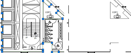
 Once I received their drawing, I used the Selection Cycling feature (see Michael's Corner, August 2012) and discovered the Wipeout object.
A practical application of the Wipeout object would be with Xrefs as originally presented in Michael's Corner, February 2006, and you'll find another application for it in Michael's Corner, February 2008, when drawing reflected ceiling plans.
Insights
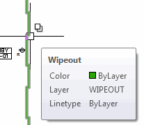
If you move your cursor over an empty area, and something highlights, you probably have a Wipeout object.
In the Wipeout command, there's an option to show the Wipeout object's frame, but not plot it.
Command: WIPEOUT

Specify first point or [Frames/Polyline] <Polyline>: F

Enter mode [ON/OFF/Display but not plot] <OFF>: D
Some people will put a wipeout object under text rather than use Background Mask in Mtext. If that's the case, and the text is in a block, use Block Editor to edit the block definition.
And if you're using a Wipeout object in your drawing, be nice and let other folks know what's going on, especially others outside your company to whom you send your drawings. “Do unto others”, and all that.
The Basics
“Best of” Basics: Irregular Viewport
When you need a viewport shape other than a rectangle, the first order of business is to be able to view the objects in Model Space at the desired scale. From there, you can create a polyline to essentially ‘crop’ the objects in Model space, then turn it into a viewport.
 The best drawing for testing this is in the path…
C:\Program Files\Autodesk\AutoCAD 20xx\Sample\Database Connectivity
If you have AutoCAD 2014 or prior, the drawing name is db_samp.DWG
If you have AutoCAD 2015 or later, the drawing name is Floor Plan Sample.DWG
How to Create an Irregular Shaped Viewport
Right-click on a layout tab and make a new layout with a large viewport.
Double-click in the viewport, then set the desired scale from the scale list on the Status bar. You may want to start with 1/64″ = 1′-0″ so you can see all of it.
Return to Paper space and create any closed polyline, spline or circle to be the viewport.
Note: If you are creating a Polyline, you must use the Close option if it is to be converted into a viewport. If you did not use the Close option, use Pedit and select the polyline, then use the Close option.
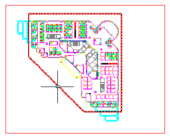
In this illustration, I created a polyline around the perimeter of the floorplan. (Ideally, this would be on a dedicated layer on which you typically create your viewports).
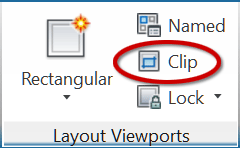 On the Layout tab, click Clip.
When prompted to select the ‘viewport to clip’, select the rectangular viewport.
When prompted to select the ‘clipping object’, select the polyline (or whatever object you created in Step 3, above).
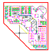
AutoCAD will convert the polyline into a viewport and erase the original rectangular viewport!
Left Field
A Final Salute to Snow: Wilson A. Bentley (1865 - 1931) took pictures of snowflakes. Lots of snowflakes. He lived in Vermont — a good place to live if you're going to do that — and there is a museum in Jericho, VT dedicated to his work.
“A self-educated farmer, Bentley attracted world attention with his pioneering work in the area of photomicrography, most notably his extensive work with snow crystals (commonly known as snowflakes).
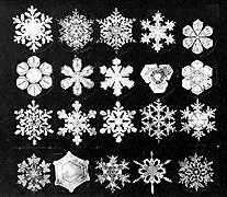 By adapting a microscope to a bellows camera, and years of trial and error, he became the first person to photograph a single snow crystal in 1885. He would go on to capture more than 5000 snowflakes during his lifetime, not finding any two alike. His snow crystal photomicrographs were acquired by colleges and universities throughout the world and he published many articles for magazines and journals including, Scientific American and National Geographic.”
http://snowflakebentley.com/
Donate to CADTutor
If you found this article useful, you might like to consider making a donation. All content on this site is provided free of charge and we hope to keep it that way. However, running a site like CADTutor does cost money and you can help to improve the service and to guarantee its future by donating a small amount. We guess that you probably wouldn't miss $5.00 but it would make all the difference to us.
Note from Michael: I want to thank all of my customers for continuing to retain my training services (some for over three decades!) and let you know your donations do not go to me personally, but to the ongoing maintenance of the CADTutor ship as a whole and to support the yeoman efforts of my friend and CADTutor captain, David Watson, to whom I am grateful for this monthly opportunity to share a few AutoCAD insights.
Share this page:


The Basics
- Dual Dimensions in a Dim…
- UCSICON Options
- "Best of" Basics: Irreg…
- Tool Palette Basics
- Original Dimension Value
- Possible Solutions to th…
- Avoid Using 'Standard' i…
- Shorten the Plot Scales…
- Update the Source File B…
- User Increment Angles fo…
- Drawing Information
- 'Sign Language'
- Rotate with the Copy Opt…
- Use the INSERT Osnap on…
- To or From the Current L…


