

 Michael’s Corner #125
May 2013
Shedding a Little Light on Things
As I get more into 3D—I know, I'm just a little late to that party—I'm finding more and more fun stuff. I'll soon have a collection to put on my own Panel on the Ribbon! I think you'll find the following to be a fun collection of insights and it even includes a wonderful improvement I found in AutoCAD 2014!
…Without a default ‘floor’, use Ground Shadows, then experiment with some Visual Style buttons
…For the macro-minded, learn how to repeat a favorite
…When you inherit a drawing with Annotative text, there's a Need-To-Know rotation setting
…Options for selecting objects, including a really great improvement in A2014
Keep in mind that Autodesk has a YouTube channel in case you want to find more out about the new fleet of products available.
Here's to greater productivity for us all!
If you would like to contact me directly, you can do that also.
Blessings to one and all,
Michael
Shadows & Visual Style Settings
 By default, when you draw objects in AutoCAD, it's difficult to discern if they are ‘sitting’ on the surface of the current XY plane or if they're suspended, or maybe even below that surface. Not long ago, I came across a delightfully informative video tutorial about ground shadows on the CADTutor site, hosted by the captain of the CADTutor ship, Professor David Watson.
Additionally, I want to point out a couple other features, all of which can be found on the Visual Styles panel of View tab of the Ribbon [Drafting & Annotation workspace]… all the way back to AutoCAD 2011!
But first…
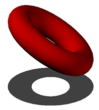
How to Create, Edit, & Display a Torus
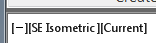
Use the Viewport controls in the upper left corner of the drawing window to change to an isometric view.
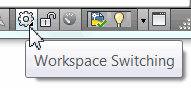
On the status bar, click Workspace Switching, then 3D Modeling.
 On the Solid tab
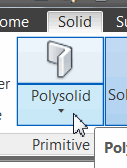
 Primitive panel (beginning in A2012), expand Polysolid, then click Torus.
The Torus is a 3D donut (I know, this is the 2nd month where I'm talking about donuts). The first 2 points you specify in this command is the radius of the donut, then the 3rd point will be for the diameter of the ‘tube’.
Pick the three points that will define the donut. By default, only the upper half of the torus is above the XY plane.
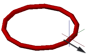
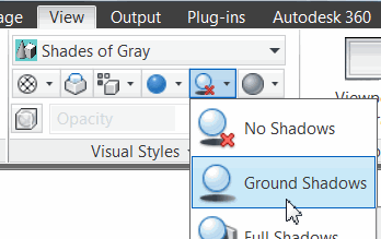
On the View tab, Visual Style panel, click the Shadows dropdown button, then click Ground Shadows. Since the lower half is below the XY plane, you won't see the shadow… yet.
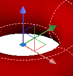 Click once on the torus to display the (very colorful) 3D Gizmo. [For those of you who have my book, The AutoCAD Workbench, 2nd Edition, you'll find this coverage on page 263. Subtle, right?]
Hover on the vertical blue axis to display the blue vector, then click on it and move the torus in the Z direction. You don't have to go far to see the ground shadow!
To rotate the torus, right-click anywhere on the axes of the gizmo to display the shortcut menu, then click Rotate.
Click and drag one of the ‘hoolahoops’ to rotate the torus.
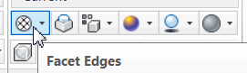
And finally, with the exception of the Hide button, the four other features that accompany the Shadows button result in some very unique graphic representations of your solids.
Power Tool
Repeat a Command in a Macro
Many of you have been quite prolific in creating buttons for the tool palette and other customizable areas, so you may find this insight rather useful: To repeat a macro, put an asterisk in front of the ^C^C. Specifically, *^C^C
Just to get the hang of it, put the following in the Command String field of a blank button on the tool palette.
As has been mentioned in previous articles, the semi-colon presses [Enter], the backslash pauses for user input.
*^C^CROTATE;\\;\\MOVE;P;;\\
Breakdown
| ROTATE; | Types Rotate, then presses Enter |
| \\; | Allows for 2 corners to be specified—Crossing or otherwise—to select the objects, then presses Enter |
| \\ | Allows for the 2 points for the rotation process—base point, then pick a rotation angle |
| MOVE; | Types Move, then presses Enter |
| P;; | Runs the ‘Previous’ object selection method, then presses Enter |
| \\ | Allows for the 2 points for the move process—from where, to where |
| Automatically repeats because of the asterisk preceding the routine |
If nothing else, it's kind of fun to see how it works!
The Odd Spot
Annotative Text that Doesn't Rotate "Normally"
Here's one I hadn't seen before.
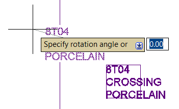
Attempt to rotate text and it acts like a ride at the County Faire; the text object maintains the default orientation, but rotates positionally around the base point.
Quick Properties Solution
Not being an Annotative Text fan, I didn't realize there's an annotative text setting that causes that response in text objects that are rotated.
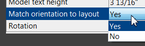
In Quick Properties I discovered that the Match Orientation to Layout setting was set to Yes. The alternative solved the problem and the customer was then able to rotate the text normally.
You also have that option in the standard Properties window, but I typically start with Quick Properties to see what's available.
The Basics
Selection Options & A2014 Improvements
By default…
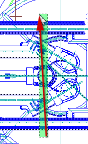
If you pick air and go right, you create a Window (a solid blue box). It will select only those objects completely within the window.
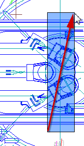
If you pick air and go left, you create a Crossing window (a dashed green box). It will select anything the dashed box crosses, as well as anything inside the resulting window.
Significant AutoCAD 2014 Improvement
Notice in the figures that the objects which will be selected are highlighted BEFORE committing to the second corner! I love this!
Additional Selection Options
The following options hold true for any editing command requiring object selection. Any of these options may be entered at the "Select objects:" prompt…
Fence is a crossing line which selects objects crossed by the fence after you press <Enter>.
WPolygon selects all entities within the boundaries of a polygon created by points you input.
CPolygon selects all entities within or touching the boundaries of an irregular polygon.
Last selects the "youngest" object (singular) displayed.
Previous selection set.
Use Shift + Pick to deselect object(s).
ALL selects all entities within your drawing whether or not they are visible on your display.
Note Regarding Selecting Wide Polylines and TrueType Fonts
When selecting a wide polyline or text using a TrueType font such as Arial, pick the edge of the object, not the middle.
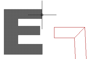
As shown in the figure, the ‘E’ is highlighted when you're on the edge of the character. The angled, red shape is the outline of a wide polyline with the variable FILL set to <OFF>.
Bottom line, the colorful middle of these objects is fluff; not tangible.
Left Field
The Logo: The new Autodesk logo was unveiled in February at the ‘premiere conference about technology, entertainment, and design’, oft referred to as—with no other reference, because surely you must know what it means—TED. For more on the coverage of that auspicious event and some thought behind the logo's development, here's a link to the Autodesk News and Opinions page, In the Fold.
Donate to CADTutor
If you found this article useful, you might like to consider making a donation. All content on this site is provided free of charge and we hope to keep it that way. However, running a site like CADTutor does cost money and you can help to improve the service and to guarantee its future by donating a small amount. We guess that you probably wouldn't miss $5.00 but it would make all the difference to us.
Note from Michael: I want to thank all of my customers for continuing to retain my training services (some for over three decades!) and let you know your donations do not go to me personally, but to the ongoing maintenance of the CADTutor ship as a whole and to support the yeoman efforts of my friend and CADTutor captain, David Watson, to whom I am grateful for this monthly opportunity to share a few AutoCAD insights.
Share this page:


The Basics
- Dual Dimensions in a Dim…
- UCSICON Options
- "Best of" Basics: Irreg…
- Tool Palette Basics
- Original Dimension Value
- Possible Solutions to th…
- Avoid Using 'Standard' i…
- Shorten the Plot Scales…
- Update the Source File B…
- User Increment Angles fo…
- Drawing Information
- 'Sign Language'
- Rotate with the Copy Opt…
- Use the INSERT Osnap on…
- To or From the Current L…


