

 Michael’s Corner #70
October 2008
QBSF*
My birthday is on traditional Columbus Day, so I would first like to send out birthday wishes to all of you October 12th folks. 55, thank you… and cards are welcome.
Customizing takes over again this month as I bring my monthly Tool Palette button to the front of the pack in an effort to help those of you who are doing area hatches for Phasing or Departments on a floorplan. Then I was thinking about how to automate the cool Quick View Drawings command without putting it on a palette… and thought it would be cool to put it on a Function key, say, for example, that one we all love to hate - F1.
In the Odd Spot I make a quick mention of one of those things that will mess with your head until you finally realize what's going on (see below), and then I wrap it up with a review of the Perpendicular object snap in the Basics.
* Quicker, Better, Smarter, Faster. I made that up. You can use it.
If you would like to contact me directly, you can do that also.
Blessings to one and all,
Michael
Select Objects for a Hatch on a Button
 In my training sessions, I usually show my customers how you can drag a hatch directly from the drawing and release it on the tool palette. Very cool and very easy. The downside is, when you go to place that hatch into a drawing, you don't have the option to select the objects to hatch, it's a "drag 'n' drop" interface. Consequently, if you have objects within the area being hatched, they're treated as islands and you have a different set of issues.
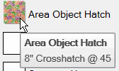
This month, I'm bringing the button article to the front to illustrate how to preset Hatch variables, then select the object(s) to be hatched.
Some of the variables we'll be using in the macro were actually referenced back in my second month of Michael's Corner, February 2003. Here are the ones we will be setting in this routine.
| HPNAME;"USER" | User-defined hatch so you can specify spacing and angle |
| HPSPACE;8 | Spacing between the lines of the hatch |
| HPANG;45 | Angle of the hatch |
| HPDOUBLE;1 | Double-hatch |
| HPSEPARATE;1 | Creates separate hatches if you select more than one object to hatch |
For this exercise, you'll need an empty button on a tool palette that you will customize with the macro. To add an empty button to your tool palette, take a look at Michael's Corner Odd Spot, April 2007.
Instructions to Create a Button to Add a Hatch to the Selected Object
- Open the Tool Palettes window (Ctrl + 3), then click the palette onto which you would like to add this button. If you've been following along with my articles the over the last year (since last October when I began this series) you should have a pretty good collection of buttons by this time.
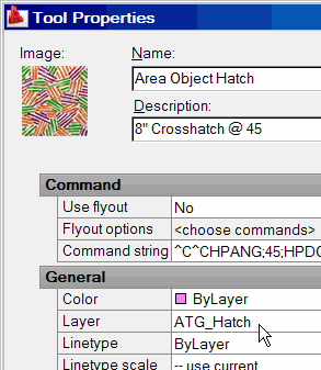
- Add a blank button to your tool palette, then right-click on the button and click Properties to open the Tool Properties window for that button.
There are two approaches to running commands from a macro. You could either A) Specify the relevant variables prior to running the command, or B) Use the options of the command to specify the options. In this macro, I have opted to establish the variables listed above prior to running the Hatch command. That way, my "homework" is done and I just respond to the default prompt for selecting the object to hatch.
Next, when running a macro, if the routine encounters a dialog box, the macro comes to a screeching halt and can go no further. Therefore, the following macro launches the command line version of the Hatch command by putting a hyphen before the command name. This applies to numerous commands that, by default, invoke a dialog box. Try -Layer for the Layer command, -Insert for the Insert command, -View for the View command, and -Hatch for the Hatch command.
- In the Command String box, enter the following (or just copy this string):
^C^CHPNAME;"USER";HPSPACE;8;HPANG;45;HPDOUBLE;1;HPSEPARATE;1;-HATCH;S;\;;
You will notice that -HATCH is used to issue the command line version of the Hatch command. The remaining characters and their function are:
| S | Issues the Select Objects option of the Hatch command |
| ; | Use a semi-colon to press Enter |
| \ | Backslash pauses for user response |
To complete your button, I would recommend you set the desired Layer, Color, and Linetype.
To put a picture on your button, right-click on the blank image box in the upper left corner of the Tool Properties dialog box and click Specify Image. Navigate to any location where you have a BMP, JPG, PNG, GIF or TIF file that you would like to use as the button image.
Power Tool
Quick View Drawing to F1
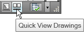 The AutoCAD 2009 feature called "Quick View Drawings" is very cool and has been readily accepted by my customers now on that version. To access the feature, however, you have to click the Quick View Drawings which is down on the status bar. I thought it would be really cool if maybe we could put that command on a rarely used (or cared about) key on the keyboard… such as F1!
Note: In December 2005 I also covered how to assign a value to the F1 key, however, it never hurts to go back over cool customizing features. And if you have yet to get your A2009, you can use any command in the following exercise in place of Quick View Drawings.
Instructions to Assign "Quick View Drawings" to F1 [A2009]
- Open the Tool Palette window, then you will need a blank button to work with (see Michael's Corner Odd Spot, April 2007).
- Open the CUI dialog box by typing CUI at the command line, or right-click on any button, then click Customize.
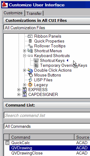
- In the Customizations pane, expand Partial CUI Files, then expand Custom. Now expand the Keyboard Shortcuts node.
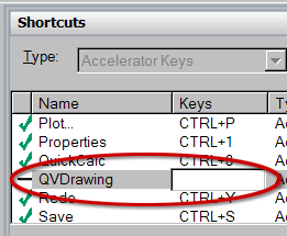
- Under Command List, drag the QVDrawing command up into the Customizations pane and release it next to Shortcut Keys to add it to the listing.
Note: If the recently added command does not initially appear in the Shortcuts pane, you may have to OK out of the CUI, then re-open it.
- In the Shortcuts pane next to the Distance command, click in the Keys column to display an edit box, then press F1 and press <Enter>. You should now see a green checkmark in the column preceding the Distance command name.
- Click OK to close out of the CUI, then hit F1… to launch the Quick View Drawings command rather than the Help window!!
The Odd Spot
Locked Vport Layer
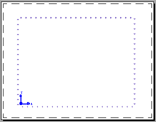
This is a relatively rare occurrence, but it's important to know that if you lock the layer on which the viewport "frame" has been created, when you double-click into that viewport, the frame will appear dotted. One of my customers bumped into this and once we found out what was causing the frame to be dotted, I made a note to pass it along.
The Basics
Snap to Perpendicular
 My most common application for using the Snap to Perpendicular feature is when I'm creating polylines on a floorplan for area calculations. Areas for Accounting, Admin, Reception — things like that. Or perhaps you're indicating the area for Phase I or Phase II. In these situations, you won't always have places like Endpoints or Midpoints to snap to, but it would be handy to snap to the point that's perpendicular to a specific wall.
To refine the application further, Snap to Perpendicular is particularly helpful in a floorplan that is not made up of perfectly orthogonal walls or surfaces. In those situations, Object Snap Tracking (Otrack) would be an alternative (see Basics, September 2007).
 Memo: My recommendation would be to use Snap to Perpendicular only when needed. In other words, I would not set it as a permanent Osnap setting. To that end, there are two ways you may want to consider when accessing the Perpendicular snap.
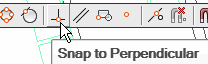
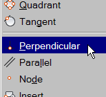
One way may be to dock the Object Snap toolbar (shown above) somewhere around the edge of your drawing window. Object snaps used from that toolbar are good for one hit only. The other option would be to hold down Shift (or Ctrl), then right-click. By default, this mouse/key combination will always display the shortcut list of Object snaps.
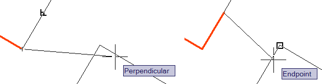
In the first figure, Snap to Perpendicular has been initiated and the cursor is placed close to the line whose extended vector would intersect the target line. Once the vector of the line has been acquired, a Perpendicular tool tip appears on the target line at the point where the vector of the acquired line would intersect the target line at a 90 degree angle. When you see the Perpendicular tool tip, click your cursor to place the point.
The second figure indicates the placement of the point of the polyline at the location of the Perpendicular tooltip, and at this point (so to speak), you can continue placing points of the polyline.
Note: Snap to Perpendicular is helpful when using the Move or Copy command, too.
Left Field
Got old hardware? - I'm not sure where I heard about this website, but in an effort to do my part for the "Green" movement, I want to encourage you to check out www.computertakeback.com to learn how you can be more earth-friendly with those old computers (and TV's!) you have.
Donate to CADTutor
If you found this article useful, you might like to consider making a donation. All content on this site is provided free of charge and we hope to keep it that way. However, running a site like CADTutor does cost money and you can help to improve the service and to guarantee its future by donating a small amount. We guess that you probably wouldn't miss $5.00 but it would make all the difference to us.
Note from Michael: I want to thank all of my customers for continuing to retain my training services (some for over three decades!) and let you know your donations do not go to me personally, but to the ongoing maintenance of the CADTutor ship as a whole and to support the yeoman efforts of my friend and CADTutor captain, David Watson, to whom I am grateful for this monthly opportunity to share a few AutoCAD insights.
Share this page:


The Basics
- Dual Dimensions in a Dim…
- UCSICON Options
- "Best of" Basics: Irreg…
- Tool Palette Basics
- Original Dimension Value
- Possible Solutions to th…
- Avoid Using 'Standard' i…
- Shorten the Plot Scales…
- Update the Source File B…
- User Increment Angles fo…
- Drawing Information
- 'Sign Language'
- Rotate with the Copy Opt…
- Use the INSERT Osnap on…
- To or From the Current L…


