


Michael’s Corner
 Michael's Corner is a monthly publication written by Michael E. Beall, Autodesk Authorized Author and peripatetic AutoCAD trainer. Michael travels all over the USA, bringing his fantastic experience and great understanding of AutoCAD to his clients. Michael's Corner brings together many of the tips, tricks and methods developed during these training sessions for the benefit of all users.
Michael's Corner provides something for every AutoCAD user. Every month, a number of articles cover a wide range of topics, suitable for users at all levels, including "The Basics" for those just starting out. Essentially, the aim of Michael's Corner is to help all AutoCAD users work smarter and faster.
This month…
October - One-derful!!!
It's a God-thing.
I had no idea that 14 years ago I would be given the opportunity to make an impact on the professional lives of so many. Only God knew what was ahead, and hopefully, the contributions I have made through Michael's Corner have equipped many of you to be more productive and a bit more savvy using AutoCAD. And apart from all the AutoCAD bashing that is going on, I'm sure it has a long life ahead.
So, in an effort to keep the AutoCAD fires burning, here's what I have for my final installment…
…A reminder on how to customize your hot keys
…Three Power Tools — one for Zoom, one for editing, and one for Layers
…Two Odd Spots — one for Layers and one for Hatching
…Buried text treasure
…And how to Search 14 years of the Archives
As for what's ahead for me, I will continue to present a variety of AutoCAD sessions — Fundamentals, Intermediate, Customizing, Updates, and 2D & 3D. I will also keep training CAP Designer, 20-20 Worksheet, Visual Impression (those three from 20-20 Technologies, Inc.), and some Revit Fundamentals. Next year I'm looking forward to being very involved in training CET (from Configura, Inc.) when Herman Miller joins the growing number of manufacturers embracing this software that is being touted as the ‘Future of Space Planning’. Personally, I'm looking forward to spending a bit more time with Donna, my lovely bride of 30 years. When this posts, we'll probably be within days of going on our 30th Anniversary vacation to the Tanque Verde Ranch in Tucson; Ee-Hah! We had such a good time when we went for our 20th, we figured we'd do it again!
Ah, and I'm hoping to have The AutoCAD Workbench, Final Edition out before snow flies.
And with that, Mike drop! …so to speak.
The LORD bless you and keep you;
The LORD make His face shine upon you,
And be gracious to you;
The LORD lift up His countenance upon you,
And give you peace. Numbers 6:24-26
This month's articles
Change F1 to ESC
Smoother Zoom
Stretch with Extension
Lock Layers with a Crossing Window
Layer Columns & Hatch Background Color
Text Frame on Mtext
From the Vault
Snap From or… “Put it this far from here”
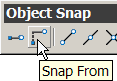 How many times have you had to place a fixture, a bracket, the center of a circle, a column or do anything based upon an existing point? The Snap From feature has been around for years but when I show it to my customers, they're always amazed. Use it in any procedure, drawing or editing, in which you need to place a point on the screen, can use this feature. You launch it when AutoCAD is asking you where you want to place the point in question.
Instructions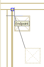
Say I'm moving column and I've picked the base point and now AutoCAD wants to know the "Second point of displacement", do this…
- Choose "Snap From" from the Object Snap toolbar or type FRO at the prompt.
- You now get a prompt for a "Base point", pick the point from which you will enter an offset distance for the new position, as shown in this figure.
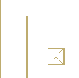
- When prompted for the <Offset>, enter the displacement from the base point in the format @X,Y. This syntax effectively states that from where I'm "at". To place the column, I entered @4',-4' as shown in the final figure.
The Basics
- Dual Dimensions in a Dim…
- UCSICON Options
- "Best of" Basics: Irreg…
- Tool Palette Basics
- Original Dimension Value
- Possible Solutions to th…
- Avoid Using 'Standard' i…
- Shorten the Plot Scales…
- Update the Source File B…
- User Increment Angles fo…
- Drawing Information
- 'Sign Language'
- Rotate with the Copy Opt…
- Use the INSERT Osnap on…
- To or From the Current L…


